The MOT Inspection Manual: Classes 3, 4, 5 and 7
Last updated by DVSA on 1 April 2026
Content published by DVSA and obtained under the Open Government Licence v3.0.

Inspection processes and rules for MOT tests on cars, private buses, light goods vehicles and related classes.

Introduction
An introduction to the Inspection Manual
Definitions, vehicle classes, reasons to refuse to test a vehicle, narrow track vehicles, historic vehicles and inspection procedures for car and passenger vehicle MOT tests.

1. Abbreviations and definitions

Abbreviation or term Definition
abandon When a test cannot be completed because the tester thinks it’s unsafe to continue or because it becomes apparent during the test that certain items cannot be satisfactorily inspected. An appropriate fee may be charged for the test.
abort When a test cannot be completed because of a problem with the test equipment or the tester. No fee may be charged for the test.
AE Authorised Examiner - the organisation that operates and manages one or more VTS and is responsible for controlling the quality of testing carried out. Except in the case of a ‘sole trader’ the AE is not a person but a legal entity, such as a company or partnership.
ATL Automated test lane - lanes authorised by DVSA which use wheel play detectors and an automated roller brake tester
bodied vehicles A bodied vehicle has a floor pan and surrounding panels. The vehicle may or may not have a roof. As a guide, if the driver sits in the vehicle with surrounding structure it would be classed as bodied.
bus A motor vehicle which is constructed or adapted to carry more than 8 seated passengers (see also ‘minibus’)
category L2e vehicle A three-wheeled vehicle (tricycle) classed as a moped – a maximum speed not exceeding 45km/h, not more than 50cc for spark ignition engine or 4KW for any other power unit
category L5e vehicle A three-wheeled vehicle (tricycle) more than 50cc and/or a maximum speed greater than 45km/h
category L6e vehicle (light quadricycle) Four-wheeled vehicle with a max ULW of 425kg, max speed of 45km/h. fitted with a spark ignition internal combustion engine having a cylinder capacity not exceeding 50cc or fitted with any other internal combustion engine which has a maximum net power output of 4kW or fitted with an electric motor with a maximum continuous power not exceeding 4kW. Sub classification category L6e-BP / L6e-BU vehicle equipped with a maximum of two seating positions, including the seating position for the driver and enclosed driving and passenger compartment, accessible by maximum three sides and maximum continuous rated or net power 6 KW These vehicles can be identified by the vehicle type-approval number recorded on the manufacturers plate (L6e-BP / L6e-BU)
category L7e vehicle (heavy quadricycle) Four-wheeled vehicle with a max ULW of 450kg (600kg for goods vehicles), fitted with an engine having a cylinder capacity of more than 50cc if of the internal combustion type, and/or a maximum design speed of more than 45 km/h, the maximum net engine power not exceeding 15kW, if designed to carry goods a payload not exceeding 1000kg
category M1 vehicle A vehicle with 4 or more wheels used for the carriage of passengers, with no more than 8 passenger seats in addition to the driver’s seat. This includes dual purpose vehicles, motor caravans and ambulances, but does not include quadricycles.
category M2 vehicle A vehicle with 4 or more wheels used for the carriage of passengers, with more than 8 passenger seats in addition to the driver’s seat and a maximum DGW not exceeding 5,000kg. This includes dual purpose vehicles, motor caravans and ambulances.
category M3 vehicle A vehicle with 4 or more wheels used for the carriage of passengers, with more than 8 passenger seats in addition to the driver’s seat and a maximum DGW exceeding 5,000kg
category N1 vehicle A vehicle with 4 or more wheels used for the carriage of goods and having a DGW not exceeding 3,500kg. This includes dual purpose vehicles.
coach A motor vehicle constructed or adapted to carry more than 16 seated passengers, with a DGW of more than 7,500kg and a maximum speed in excess of 60mph
CT Contingency testing - the test process using paper documentation when the online MOT testing service is not available
CT20 An MOT test certificate issued during a period of contingency testing
CT30 A refusal of an MOT test certificate issued during a period of contingency testing
DGW Design gross weight - the maximum gross weight that the vehicle was designed to operate at by the manufacturer. This is normally found on the manufacturer’s plate fixed to the vehicle, or in some older or heavier vehicles on a `ministry plate’.
DVSA The Driver and Vehicle Standards Agency
large Class 4 A Class 4 vehicle with a DGW greater than 2,500kg
MAM Maximum authorised mass - the maximum gross weight permissible in Great Britain
MIL Malfunction indicator lamp
minibus A motor vehicle constructed or adapted to carry more than 8 but not more than 16 seated passengers (see also ‘bus’)
ministry plate Displays the maximum authorised weights at which a vehicle may be operated. This information supersedes the maximum weights displayed on the manufacturer’s plate.
MOT Testing Guide An online handbook for MOT scheme administration
MOT testing service Internet based system for registering MOT tests, producing MOT documentation and performing certain administrative functions
OPTL One-person test lane - authorised by DVSA to conduct testing where the tester can conduct a test without an assistant
QC Quality control
special notice An official notice by DVSA to inform AEs, NTs and other system users of changes and developments to the testing scheme or highlight areas of concern
test All statutory tests recorded on the MTS database, regardless of whether the test is a full test or a retest. Further information on retests is provided in Section 19 of this Introduction
ULW Unladen weight - the weight of a vehicle inclusive of the body and all parts which are ordinarily used with the vehicle when working on a road. Unladen weight does not include the weight of water or fuel used for the propulsion of the vehicle, or of loose tools and loose equipment.
VT20 An MOT test certificate which includes the Welsh language version (VT20W)
VT30 A notice of refusal of a MOT test certificate including the Welsh language version (VT30W)
VTS Vehicle Testing Station
V5/V5C Vehicle registration certificate issued by the Driver and Vehicle Licensing Agency
you MOT tester

2. Application (Classes 3, 4, 5 and 7)

This manual is a detailed guide to the inspection for statutory MOT testing of the following classes:

Class Vehicle type
Class 3 Three-wheeled vehicles not exceeding 450kg ULW (excluding motorcycle combinations) - category L2e or L5e
Class 4 Three-wheeled vehicles more than 450kg ULW - category L5e
Quadricycles - category L6e or L7e
Cars and Taxis - category M1
Minibuses, motor caravans, dual purpose vehicles and ambulances up to 12 passenger seats - category M1, M2 or N1
American pickups up to 6500kg DGW
Goods vehicles not exceeding 3,000kg DGW - category N1
Class 5 Private passenger vehicles, ambulances and motor caravans with 13 or more passenger seats - category M2 or M3
Class 7 Goods vehicles between 3,001kg and 3,500kg DGW inclusive - category N1
Please note: If a goods vehicle is presented with a manufacturer’s plate and a ‘ministry plate’ the weights to be used are those on the ‘ministry plate’

Diagram 1. Example of a class 4 manufacturer’s plate example of a class 4 manufacturer's plate

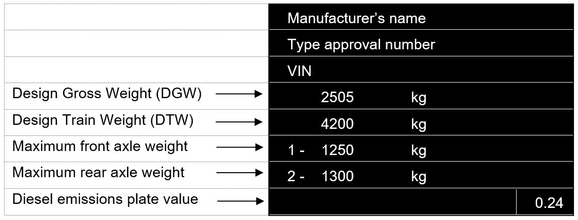
Some plates may not state the axle number, but vehicle weights will generally be displayed in this order.

Some manufacturers plates may not display a Design Train Weight (DTW) as they have not been designed or constructed to tow trailers.

Some Class 7 testing stations are approved to test Class 5 vehicles with a DGW up to 5,000kg referred to as Class 5L (category M2). Class 5L does not include any vehicle that must have a seatbelt installation check. Such vehicles must be presented at a Class 5A testing station.

Definitions of sub-Classes 4A and 5A are given in the MOT Testing Guide.

Dual purpose vehicles are defined in the MOT testing guide. The unladen weight of a dual-purpose vehicle must not exceed 2,040kg. However, 4 × 4 pickup and crew cab type vehicles with a DGW over 3,000kg up to and including 3,500kg are considered dual purpose vehicles for test purposes if information about the unladen weight is not available.

Diagram 2. Flow chart to identify a dual purpose vehicle test class flow diagram to identify a dual purpose vehicle

American pickup means a motor vehicle manufactured in the United States of America or Canada that meets all of the following criteria:

  • it’s capable of carrying a driver and at least one passenger
  • it’s capable of carrying goods in an open load bed separate from the driver/passenger compartment, with or without a removable cover
  • it has a gross design weight over 3,000kg but does not exceed 6,500kg

Pickup vehicles with a fifth-wheel should not be considered articulated vehicles. They should be tested as normal.

To determine the seating capacity of a passenger vehicle, the number of occupied wheelchairs that can be carried should be added to the number of seats.

Other than for the inspection of tyres, any 2 wheels of a vehicle shall be regarded as one wheel if the distance between the centres of the areas of contact between such wheels and the road surface is less than 460mm. You should be aware that this may affect the test class. For example, a three-wheeled vehicle with a wheel layout meeting this criterion must be tested as a motorcycle.

Tricycle and quadricycle test classes

Vehicle type Description Test class
three-wheeled moped (L2e) Three-wheeled vehicle with a max speed of 45km/h, not over 50cc for a petrol engine or 4KW for any other engine or electric motor, not more than 450kg ULW 3
motor tricycle (L5e) Three-wheeled vehicle with wheels symmetrically arranged, a max speed over 45km/h, or engine size over 50cc, not more than 450kg ULW 3
motor tricycle (L5e) Three-wheeled vehicle with wheels symmetrically arranged with a max speed over 45km/h, or engine size over 50cc, more than 450kg ULW 4
light quadricycle (L6e) Four-wheeled vehicle with a max ULW of 425kg, max speed of 45km/h. fitted with a spark ignition internal combustion engine having a cylinder capacity not exceeding 50cc or fitted with any other internal combustion engine which has a maximum net power output of 4kW or fitted with an electric motor with a maximum continuous power not exceeding 4kW. Sub classification category L6e-BP / L6e-BU vehicle equipped with a maximum of two seating positions, including the seating position for the driver and enclosed driving and passenger compartment, accessible by maximum three sides and maximum continuous rated or net power 6 KW These vehicles can be identified by the vehicle type-approval number recorded on the manufacturers plate (L6e-BP / L6e-BU) 4
heavy quadricycle (L7e) Four-wheeled vehicle with a max ULW of 450kg (600kg for goods vehicles), fitted with an engine having a cylinder capacity of more than 50cc if of the internal combustion type, and/or a maximum design speed of more than 45 km/h, the maximum net engine power not exceeding 15kW, if designed to carry goods a payload not exceeding 1000kg 4

If any of the above vehicles are electrically powered, their unladen weight must not include the weight of the batteries.

If there is significant doubt about the power output or the weight of the vehicle, the presenter must provide documentary evidence.

If the vehicle is too heavy or powerful to qualify as an L7e quadricycle it is an M1 vehicle and must be tested as if it was a car, for example, it must meet the full lighting, brake efficiency and emissions requirements

3. Vehicles of historical interest (over 40 years old)

Some vehicles of historical interest may be exempt from statutory MOT testing. Such vehicles must be over 40 years old and not substantially changed.

Owners of these vehicles may still request a statutory test be conducted. In these circumstances, you must register the test on the MOT testing service and carry it out in the usual way and issue the appropriate documentation.

You should remember that certain components on historic vehicles may have been manufactured to have a greater degree of play or tolerance than is found in modern vehicles.

4. Refusal to test

Legislation permits testers to refuse to test vehicles in certain circumstances. If any of the reasons for refusal (see below) apply, you should not carry out the test and must return any fee paid for the test. You should carry out appropriate pre-checks before starting the test, to ensure the suitability and general condition of the vehicle.

If the vehicle presenter needs written confirmation of why the test cannot be carried out, you should register the test using the MOT testing service and issue a VT30 clearly showing the reason(s) why the test could not be carried out.

If reason to refuse ‘i’ applies, you should issue a handwritten CT30 containing as many of the vehicle details as possible. A copy of the CT30 should be retained by the VTS.

The reasons for refusing to carry out the test are:

  1. a. The V5C or other evidence of the date of first use is not produced. Normally this evidence is only necessary if the vehicle has a ‘cherished’ registration mark (also referred to as personalised registration number) or if the registration mark’s year letter does not make it clear which standard should be applied.
  2. b. The vehicle or any part or equipment on the vehicle is so dirty that examination is unreasonably difficult.
  3. c. The vehicle is not fit to be driven when necessary to complete the test because of a lack of fuel, or oil, or for any other reason.
  4. d. The tester considers a load or other items, or insecurity of a load or other items, would prevent a proper test being carried out - unless the load is secured or removed.
  5. e. The VTS asks for the fee to be paid in advance and this is not done.
  6. f. The vehicle emits substantial quantities of avoidable smoke.
  7. g. A proper examination cannot be carried out because any door, tailgate, boot, engine cover, fuel cap or other device designed to be easily opened cannot be easily opened.
  8. h. The condition of the vehicle is such that, in the opinion of the tester, a proper examination would involve a danger of injury to any person or damage to the vehicle or other property.
  9. i. The vehicle has neither a registration mark nor VIN/chassis number or frame number by which it can be identified, or that all such identifications are illegible or use letters and numbers not normally used in the English language.

If despite due care initially, it becomes apparent during a test that the test cannot be completed for any of the above reasons, the test must be abandoned, or the vehicle failed because the test could not be satisfactorily completed. Any subsequent re-examination and fee must be in line with normal policy. See the MOT fees and appeals poster (VT9A) for further information.

In addition to the above reasons you must decline to test any vehicle:

  • that is not of a class you are authorised to test
  • if there is doubt about the power output (when required) or the weight of the vehicle
  • if it is of such a size, weight or configuration that it cannot be properly or safely tested on the approved facilities

There are exceptions for narrow track vehicles.

5. Narrow track vehicles

If a vehicle has a track width that is too narrow for the vehicle to be safely tested on the approved pit or hoist, the inspection can be carried out on an area of hard standing within the testing facility. However, this only applies where the headlamp aim test can be conducted using the approved equipment and with the vehicle placed in the headlamp aim standing area.

You should use appropriate test methods covering all testable items set out in the inspection manual. For checks where wheels must be raised clear of the ground, you should use a suitable jack. Turning plate checks will need to be carried out on hard standing as best as possible.

If a roller/plate brake test cannot be carried out, due to the narrow track width or the transmission type, then a decelerometer test must be conducted.

If you have health and safety concerns regarding these procedures or the suitability of the test equipment, you should decline to test the vehicle.

6. Vehicle ‘first used’ dates - Application of test criteria

Usually you’ll be given the vehicle details as part of the registration process. This will usually include the vehicle’s ‘first used’ date. If the ‘first used’ date is known, you should only use defects applicable to the vehicle’s age.

When the ‘first used’ date is not known or incorrect, you should determine the vehicle’s ‘first used’ date as follows:

  1. a. Its date of manufacture, if the vehicle was originally used without being registered in Great Britain, such as an imported vehicle or ex-HM Forces vehicle.
  2. b. Vehicles having a Q plate registration when presented for MOT are to be treated as follows:
    1. -for emission purposes only, they are to be considered as first used before 1 August 1975
    2. -for all other testing purposes, they are to be considered as being first used on 1 January 1971
  3. c. In any other case, the earlier of either its date of first registration or the date 6 months after it was manufactured, for example, vehicles first used before 1 September 2001 do not need to have anti-theft device. However, a vehicle first used after that date, but manufactured at least 6 months before that date (before March 2001) would still not need an anti-theft device to be fitted.

You should enter this information onto the MOT testing service so that you can select the appropriate defects.

7. The MOT inspection manual

Although this manual is publicly available, it’s specifically written for MOT testers. It specifies the applications, procedures and standards to be used for MOT testing. You must read it with any current special notices relevant to the class or type of vehicle under test.

You should familiarise yourself with the contents of the manual and any amendments to it, including special notices which affect test procedures or standards.

Defects found during the MOT test will be categorised in one of the following groups:

  • minor - defects that have no significant effect on the safety of the vehicle or impact on the environment and other minor non-compliances
  • major - defects that may prejudice the safety of the vehicle, have an impact on the environment, put other road users at risk or other more significant non-compliances
  • dangerous - defects that are a direct and immediate risk to road safety or having an impact on the environment

If a vehicle has only minor defects, it will pass its MOT inspection and a test certificate will be issued. If a vehicle has any major or dangerous defects, it must be failed and a refusal notice issued.

8. Vehicle technical data

The MOT testing service may give testers technical information about certain vehicles under test. This is to help testers choose the correct the test methods and/or apply the correct standards.

9. The MOT testing guide

The MOT testing guide explains what is required of persons and organisations authorised to conduct statutory tests on certain motor vehicles. It also includes, among other things, information on the administration of the MOT scheme, disciplinary procedures and equipment calibration requirements.

10. Assessment of component condition

It is not practical to lay down limits of wear and tolerance for all types of components on different models of vehicle, or to define acceptable amounts of damage, deterioration and effectiveness.

You are therefore expected to use your knowledge, experience and judgement to assess if the condition of a component has reached the stage where it’s obviously adversely affecting its functionality or likely to adversely affect the roadworthiness of the vehicle.

11. Definition of insecure

The term ‘insecure’ is used throughout this manual to describe a defective condition. This term should be taken to mean one of the following:

  • a component has relative movement (looseness) at its fixings where there should be none
  • a component has relative movement (looseness) to an associated component where there should be none
  • a safety critical component (braking, steering or suspension system component) is not safely or completely attached at its fixing or to an associated component

In determining whether a component in a safety critical system is safely attached, consideration must be given to the function of the component and the overall number of securing devices. For example:

  • a missing brake pipe clip does not necessarily mean the brake pipe is insecure if the brake pipe remains adequately supported
  • a suspension bracket with one of many securing bolts loose does not necessarily mean the bracket is insecure if it remains adequately secured with no signs of visible movement

Certain components, such as wheel fixings, batteries, body mountings have specific criteria detailed in the manual.

12. Unsafe modification

Modifications to vehicles must be assessed on their merits, taking account of the nature of the modification and whether the component is critical to safety.

A modification is unsafe if it:

  • adversely affects the roadworthiness of the vehicle
  • is likely to cause injury, such as modification to the body
  • has a disproportionately adverse effect on the environment

13. Extensively modified vehicles

If a vehicle has been extensively modified or converted, certain defects, such as for components ‘missing where fitted as standard’ should not be applied, for example:

  • a car converted for competition rally use must have the rear seats removed, be fitted with a roll cage and full harness seat belts, may not be fitted with components such as brake servo, power steering or airbags
  • a car converted to a stretch limousine may no longer be fitted with items such as curtain airbags or a functional electronic stability control system

This exemption does not apply to vehicles with minor modifications. Therefore, a car fitted with rally style seats, body kit and a sports steering wheel would not be exempt from the requirement to have a driver’s airbag if one was fitted as standard equipment.

Vehicles modified for disabled use must be assessed on their merits. For example, it’s acceptable for the driver’s airbag to be removed for a wheelchair user, but the SRS warning lamp must not indicate a system malfunction.

14. Inspection procedure

You are advised to carry out pre-checks to ensure the general condition and suitability of the vehicle for test. Other than when using a CT code, a test must not commence until you have registered the vehicle for test in the MOT testing service (see MOT Testing Guide).

When registering a vehicle for test, the actual details from the vehicle must be used. It is not acceptable to use details from other sources such as the V5C, job card or previous electronic record.

The tester who registered the vehicle for test must personally carry out the test, using the approved equipment, without avoidable distraction or interruption and only the tester is empowered to make decisions about the test results. Unless the test facility is approved for one-person testing, the tester must use a suitable assistant for certain parts of the inspection.

Although no assistant is generally required for one person test lanes, one must be used if it is necessary to conduct a proper inspection.

If you, or your assistant, are not familiar with the controls of a vehicle, you should ask the vehicle presenter to operate or demonstrate the controls.

It may be convenient to conduct the emissions test at the beginning of the inspection if the engine is still warm.

Small tools, such as pinch bars, levers and the corrosion assessment tool must be used where necessary. A hand-held inspection mirror may be used to facilitate the inspection but is not mandatory.

The MOT test must be carried out without dismantling, so it is not always possible to inspect some testable items. Bonnets, engine covers, luggage compartments, access flaps and passenger compartment doors must be opened when it’s necessary to inspect testable items.

Some access panels are secured with twist lock clips or similar and are designed to be opened easily to allow access to serviceable components and testable items. Where it is necessary to gain access to testable items covered by this type of access panel, a tester must open and close these access panels as part of the inspection.

If for example a bonnet, door or access panel designed to be easily opened cannot be opened, so preventing access to a testable item, you must either abandon or refuse to carry out the test.

You should take care when jacking up vehicles to avoid causing damage and refer to manufacturers’ information if available. Particular care is needed when jacking vehicles fitted with pneumatic, hydraulic or self-levelling suspension.

Once the inspection is completed, you must record the test results using the MOT testing service (see MOT Testing Guide).

If testing under CT, you must calculate the brake efficiencies and retain the readings for later data entry. You should record all results on the VT29 and retain any printout. Refer to the MOT testing guide for a full explanation of CT procedures.

Diagrams 2 and 3 (see below) show a typical inspection routine. These routines may need to be varied to suit different test bay layouts and equipment types. It’s recommended that you do not carry out the brake performance test until after the rest of the inspection to prevent an unknown defect causing injury to a person, damage to the vehicle or other property.

Diagram 3. Topside inspection routine Diagram of the recommended topside inspection routine

Diagram 4. Underside inspection routine Diagram of the recommended underside inspection routine

Operations

  1. With the wheels in the straight-ahead position and supporting the vehicle weight, inspect the vehicle underside following the routine shown. If using a lift for the underside inspection, it’s recommended that the rear wheels are chocked whilst the lift is raised.

  2. Jack up the front and rear wheels to check relevant items. For vehicles with a DGW exceeding 5,000kg only jack the front wheels.

  3. Carry out the headlamp aim check and brake performance test at a convenient point in the routine depending on the layout of the equipment.

15. Road testing

The statutory test does not specifically include a road test of the vehicle. However, one is permitted if you think it’s necessary to check the results of an inspection. You must be properly licensed to drive the vehicle and ensure the vehicle is in a safe condition to conduct the road test.

16. Disabled driver’s controls

If a disabled driver’s controls or fitments are additional to the standard driver’s controls and they do not adversely affect the standard vehicle equipment, they are not testable items. However, if any such equipment is seen to be defective it should be reported to the vehicle presenter.

Disabled driver’s controls or fitments that replace or affect the standard controls should be tested in the normal way and any defects should be recorded in the normal way.

17. Health and safety

AEs and their staff are reminded of their obligation to adhere to all relevant health and safety legislation while MOT testing. Further advice can be obtained from your local health and safety enforcement officer or local authority environmental health officers as appropriate.

When testing vehicles with gas, fluid or air suspension, you should be aware that clearance between components can suddenly and unexpectedly change. This can present a crushing hazard if, for example, your arm is between the suspension and the body.

You should also be aware of the hazards of sudden component failure in pressurised systems

18. Recording defects

Defects covered in this manual are selected from a component-based menu system in the MOT testing service. You will first select the appropriate component from the main component list and then make further selections from the sub-menu(s). Once you’ve selected the appropriate component, a list of defects will be available for selection.

Various categories of defect may be available for the same item depending on the nature or severity of the defect - minor, major or dangerous. You must select the appropriate category, guided by the defect wording and using your knowledge, experience and judgement.

When an item is not sufficiently deteriorated to justify rejection, there may be an option to select ‘advisory’ to inform the presenter of this fact.

When only minor defects have been selected, a test certificate will still be issued. Unlike advisory items, the use of minor defects, where appropriate, is mandatory.

If you think that a defect on a non-testable item is dangerous, you should explain it to the vehicle presenter. Some defects listed in the inspection manual may not be accessible if they are not relevant due to the age or test class of the vehicle. However, advisory items (if appropriate) for these defects may still be selectable.

It is considered best practice to advise the vehicle presenter of:

  • any items which are near to, but which have not yet reached the point of test failure
  • any peculiarities of the vehicle identified during the inspection
  • any defects on non-testable items which are found during the inspection procedure

19. Retest following failure

Information on retest fees and procedures can be found in the current MOT Testing Guide and on the ‘MOT fees and appeals’ poster (VT9A). When carrying out a partial retest you must:

  • examine all the previously failed item(s)
  • examine item(s) that may have been affected by repairs
  • carry out another brake performance test and record the results in the MOT testing service, where the braking system may have been affected by the repairs
  • examine any minor defect or item advised on at the time of the initial test

If during a retest it’s clear that the vehicle has any major or dangerous defects, you must issue a new VT30.

20. Testing electric and hybrid vehicles

The high voltage components on these vehicles are often inaccessible. However, where they are accessible, they are well insulated and do not present a high risk.

It is considered best practice when testing these vehicles to avoid touching any high voltage components and wiring. High voltage wiring insulation is orange in colour so it can be easily identified, though some imported vehicles may have high voltage wiring insulation of a different colour.

Many mild hybrids only use 48V systems which may use blue coloured insulation, rather than orange, as these are not regarded as being high voltage. However, the wiring on these systems should still be avoided.

You should be mindful, especially during the under-bonnet and under vehicle inspections, that the internal combustion engine may start without warning when electrical equipment is operated or if the battery voltage drops.

Guidance for MOT testers testing hybrid, electric and hydrogen fuel cell systems.

Section 0
Identification of the vehicle
Registration plate (number plate) and vehicle identification number rules and inspection for car and passenger vehicle MOT tests.

0.1. Registration plates

You must check the registration plates on all vehicles except for:

  • unregistered vehicles
  • foreign registered vehicles
  • diplomatic vehicles
  • military vehicles

You do not need to check:

  • the supplier’s name
  • postcode
  • BS number
  • logos or emblems outside the minimum margin around the registration number

Three-wheeled vehicles that do not have a body type which is characteristic of the body of a four-wheeled vehicle do not require a front number plate. All other vehicles, including quadricycles, must be fitted with front and rear registration plates, which must both be checked to ensure the registration number displayed is the same.

Registration plates must not:

  • be obscured, excessively damaged, deteriorated or delaminated. Where a registration plate is obviously obscured by objects or attachments this will be a deficiency under defect reference (b). Registration plates obscured by tow bars are covered by section 6.1.6.
  • have background overprinting
  • have any feature or fixing that has the effect of changing the appearance or legibility of any of the characters including the use of tints or films
  • have a honeycomb or similar effect background on vehicles first registered on or after 1 September 2001 - back lit registration plates may have a honeycomb type construction which should not be confused with a honeycomb effect background

You should pay particular attention to the position of any fixing screws or bolts as well as any delamination of the number plate as this can prevent identification of the vehicle by automatic number plate recognition (ANPR) cameras which ‘see’ any non-reflective material as being black.

Registration plates may:

  • have an optional non-reflective border displayed within the margin which must be:
    • no wider than 6mm and not within 5mm of the characters on vehicles first used before 1 September 2021
    • no wider than 5mm and not within 10mm of the characters on vehicles first used on or after 1 September 2021
  • display white, grey or silver characters on a black background - only on vehicles manufactured before 1 January 1980

Registration plate characters:

  • may contain grey, possibly to achieve a 3D or highlighting effect (only on vehicles first used before 1 September 2021)
  • may be raised or 3D
  • must be the correct size, stroke width and spacing
  • must not be italic, sloping or formed using broken or multiple strokes
  • must be laid out in the correct format for the age of vehicle
  • must be formed using the prescribed font or be substantially similar to the prescribed font - as shown below

You do not have to physically measure the characters or their spacing and you should only reject them if they are obviously incorrect.

Registration plate characters

Registration plates fitted to vehicles manufactured on or after 1 January 1980 must:

  • have black characters on a white background when fitted to the front
  • have black characters on a yellow background when fitted to the rear
  • be fitted vertically, or as close to vertical as is reasonably practicable

Registration plates fitted to vehicles first registered on or after 1 September 2021:

  • all characters must be a single shade of black
  • may be raised, but the entire surface of the characters, including the sides, must be a single shade of black
  • may have an integral raised or depressed border around the number plate periphery, not more than 5mm wide and 2mm high

Registration plates may be in a single or two line formats. Additionally, a three line format is permitted on vehicles first used before 1 September 2001.

Registration plate formats

Registration plates must meet the dimensional requirements shown in the example below. However, the space between a number ‘1’ or a letter ‘I’ and another character is permitted to be proportionately greater. Vehicles with non-date related plates, such as those issued before 1963 and Northern Ireland plates must still meet the separation requirement between groups of characters where relevant.

Unless 3 line format then there should be no more than 2 groups i.e. only one treble spacing of 33mm on any plate.

Registration plate character spacing

Vehicles registered before 1 September 2001 can have larger plates fitted with characters 89mm high and other relevant dimensions that are subsequently larger.

Tricycles, quadricycles and imported vehicles that do not have the space for standard sized registration plates can have smaller registration plates.

Defect reference Defect description Category
(a) Number plate missing or so insecure that it is likely to fall off Major
(b) Number plate inscription missing or illegible Major
(c) Number plate showing an incorrect registration Major
(d) Number plate does not conform to the specified requirements Major

0.2. Vehicle identification number (VIN)

You must check the vehicle is displaying a legible vehicle identification number.

A vehicle identification number (VIN or chassis number) is required on:

  • kit cars and amateur built vehicles first used on or after 1 September 2001
  • all other vehicles first used on or after 1 August 1980

Vehicles may have the VIN displayed in more than one location, but only one VIN is required to be complete and legible.

Check that a vehicle does not have more than one VIN displayed, other than for multi-stage build vehicles. Multi-stage build vehicles can have 2 VINs, both of which may have the same last 8 digits.

When registering a multi-stage build vehicle for test, enter the last 6 digits of either VIN, along with the registration number. If the MOT testing service finds a match against either full VIN this should be accepted.

If you do not find a match in the MOT testing service, create a new vehicle record using the converter’s VIN. A converter’s serial number is not a VIN.

Defect reference Defect description Category
(a) VIN missing or cannot be found Major
(b) VIN incomplete, illegible or obviously falsified Major
(c) More than one different VIN displayed Major
Section 1
Brakes
Brake condition and operation, service brakes, secondary brakes, parking brakes, anti-lock braking system (ABS), electronic braking system (EBS) and brake fluid rules and inspection for car and passenger vehicle MOT tests.

1.1. Condition and operation

In this section


1.1.1. Service brake pedal or hand lever pivot

Defect reference Defect description Category
(a) Pivot too tight Major
(b) Excessive wear or free play Major

1.1.2. Service brake pedal or hand lever condition and travel

A brake pedal rubber is an anti-slip material and is therefore not regarded as a defect if it’s worn smooth.

A brake pedal without a rubber usually has grooves or raised sections to provide grip in wet conditions and should be rejected if it’s worn smooth. However, some vehicles may have been manufactured with a brake pedal which did not incorporate grooves or the fitting of an anti-slip material and these should not be rejected.

You should reject a brake pedal if its grooves or raised grip sections are worn smooth. However, you should not reject a brake pedal if the vehicle has been manufactured with one that does not have grooves or anti-slip material.

Often a vehicle is fitted with an aftermarket brake pedal rubber. It is not a defect if the design pattern of the brake pedal rubber is worn smooth.

A vehicle should only be failed for insufficient reserve if the pedal or lever is touching the floor/handlebar. Checks on vehicles with power-assisted braking systems should be carried out with the engine off.

It may be possible on motorcycle derived systems for the brake lever to touch the handlebar. In such cases the extent of reserve travel should be assessed during the brake test.

Defect reference Defect description Category
(a) Insufficient reserve travel Major
(b)(i) Service brake control not releasing correctly Minor
(b)(ii) Service brake control functionality of brakes affected Major
(c) Anti-slip provision missing, loose or worn smooth Major

1.1.3. Air and vacuum systems

Vehicles first used before 1 October 1937 do not need to be tested for air and vacuum systems.

A vehicle with an ULW up to and including 3,050kg, with a reservoir coupled direct to the induction manifold or a reservoir integral in a servo unit, does not need to be fitted with a warning device.

To check the build-up of air or vacuum:

  1. Completely empty the reservoir by repeatedly pressing the service brake pedal.

  2. Start the engine and run it at just below the governed speed if diesel, or at 2,000rpm if petrol.

  3. Check the time it takes for the warning device to stop operating. Pressure build-up is considered satisfactory if the warning device stops operating within:

  • 3 minutes for pressure systems
  • 1 minute for vacuum systems

For checks that require reference to a pressure or vacuum gauge warning mark, but no warning mark is present, the following reference values should be used:

  • 45psi (3.1kg/cm2 or 3 bar) for a pressure gauge
  • 10” to 12” (25 to 30cm) for a vacuum gauge
Defect reference Defect description Category
(a)(i) Insufficient pressure/vacuum assistance for less than four brake applications after the warning device has operated (or gauge shows an unsafe reading) Major
(a)(ii) Insufficient pressure/vacuum assistance for less than two brake applications after warning device has operated (or gauge shows an unsafe reading) Dangerous
(b) Time taken to build up air pressure/vacuum to safe working value not in accordance with the requirements Major
(c) Repeated operation of any ancillary air or vacuum system completely depletes the stored air or vacuum for the braking system Major
(d) Air leak causing a noticeable drop in pressure or audible air leak Major
(e) External damage likely to affect the function of the braking system Major

1.1.4. Low-pressure warning

Vehicles first used before 1 October 1937 do not need to be tested for low-pressure warning.

A vehicle with an ULW up to and including 3,050kg with a reservoir coupled direct to the induction manifold or a reservoir integral in a servo unit, is not necessarily required to be fitted with a warning device.

Warning devices may be visual or audible but only one needs to work if both are fitted.

Some vehicles with full power hydraulic braking systems will illuminate the low-pressure warning light as soon as the ignition is switched on. It is not a defect unless the warning light stays on after the engine has been started.

Defect reference Defect description Category
(a)(i) Low-pressure warning gauge or indicator malfunctioning or defective Minor
(a)(ii) Low-pressure warning gauge or indicator not identifying low-pressure Major

1.1.5. Hand operated brake control valve

All vehicles with a secondary brake control - in addition to or in place of the normal parking brake lever - must be inspected.

Defect reference Defect description Category
(a) Control cracked, damaged or excessively worn Major
(b) Control insecure on valve or valve insecure Major
(c) Loose connections or leaks in the system Major
(d) Malfunctioning Major

1.1.6. Parking brake lever or control

Vehicles first used before 1906 do not need to have a parking brake.

Some defects in this sub-section may not apply to the type of parking brake fitted.

A parking brake lever must have obvious excessive travel before being rejected.

An electronic parking brake (EPB) may apply automatically in certain conditions, such as when the ignition is switched off or when the driver’s door is opened. Testers should be aware of this throughout the test.

Electronic parking brakes must be maintained in operation by direct mechanical means, even though they are applied electronically. However, the mechanism for keeping the brakes applied is usually within brake calliper or motor gear assembly and therefore not easy to see.

Hydraulic parking brakes as an only means of operation are not acceptable on vehicles first used on or after 1 January 1968. However, they may be used to assist the application or release of a mechanical brake.

Quadricycles may be fitted with one of the following types of parking brake:

  • an over-centre lever that is mounted on handlebars
  • a gear lever that operates a cable when it’s moved into the park position
  • a transmission lock, which is the ‘P’ position on machines with continuously variable transmission (CVT)

These machines are type approved and should not be rejected for design features that prevent them from meeting the stated requirements.

If the parking brake is the ‘P’ position on the gearbox, the efficiency of the brake cannot be tested. The tester must therefore assess the brake by using a gradient (ideally 16%), or by attempting to push the machine when ‘P’ is selected.

The over-centre lever type can be brake tested as normal using one of the approved test methods.

Defect reference Defect description Category
(a) Ratchet not holding correctly Major
(b)(i) Parking brake lever pivot or ratchet mechanism obviously worn Minor
(b)(ii) Parking brake lever pivot or ratchet mechanism worn to the extent that the brake may inadvertently release Major
(c) Parking brake lever has excessive movement indicating incorrect adjustment Major
(d) Parking brake control missing, defective or inoperative Major
(e) Electronic parking brake MIL indicates a malfunction Major
(f) Parking brake is not capable of being maintained in operation by direct mechanical action only (vehicle first used on or after 1 January 1968) Major

1.1.7. Brake valves

Defect reference Defect description Category
(a)(i) Valve damaged or excessive air leak Major
(a)(ii) Valve leaking such that brake functionality is affected Dangerous
(b) Excessive oil discharge from a compressor or brake valve Minor
(c) Valve insecure or inadequately mounted Major
(d)(i) Hydraulic fluid leak from a brake valve Major
(d)(ii) Hydraulic fluid leak from a brake valve such that brake functionality is affected Dangerous

1.1.8. Not in use

1.1.9. Pressure storage reservoirs

Vehicles first used on 1 October 1937 or later must have their air and air/hydraulic braking systems inspected.

Defect reference Defect description Category
(a)(i) Reservoir has minor damage or corrosion Minor
(a)(ii) Reservoir heavily damaged, heavily corroded or leaking Major
(b)(i) Drain device on an air brake system operation affected Minor
(b)(ii) Drain device on an air brake system inoperative Major
(c) Reservoir insecure or inadequately mounted Major

1.1.10. Brake servo units and master cylinder (hydraulic systems)

Hydraulic brake fluid level checks are confined to transparent reservoirs or where an indicator is fitted. Reservoir caps should not be removed.

Many modern vehicles are no longer fitted with vacuum servos for brake assistance. They may be fitted with electronic motor assistance units that replace the vacuum servo, or full brake-by-wire systems that rely on the ESP modulator to provide the main braking effort. These can be identified without the presence of a conventional servo behind the master cylinder.

Constant resistance may be felt when fully applying the service brake pedal down to a stop, this is normal and should not be considered a deficiency with electric systems.

Brake servo checks are not required if not fitted.

A brake fluid warning lamp may be shared with other components, for example to indicate that brake pads are worn or the parking brake is applied. Class 3 vehicles are not inspected for brake fluid warning lamp.

To check the brake vacuum servo:

  1. Make sure the engine is switched off.

  2. Deplete the stored vacuum by repeatedly applying the service brake.

  3. Fully apply the brake and hold at a constant pressure.

  4. Start the engine.

  5. Note if the pedal can be felt to travel further.

Defect reference Defect description Category
(a)(i) Brake servo defective or ineffective Major
(a)(ii) Brake servo inoperative Dangerous
(b)(i) Master cylinder defective but brake still operating Major
(b)(ii) Master cylinder leaking Dangerous
(c) Master cylinder insecure Major
(d)(i) Brake fluid below minimum mark Minor
(d)(ii) Brake fluid significantly below minimum mark Major
(d)(iii) Brake fluid not visible Dangerous
(e) Master cylinder reservoir cap missing Major
(f) Brake fluid warning light illuminated or defective Minor
(g) Incorrect functioning of brake fluid level warning device Minor

1.1.11. Rigid brake pipes

If the metal brake pipes have surface dirt that needs to be removed before it’s possible to assess their condition, you can lightly scrape the pipe with a specialist brake pipe corrosion tool or the corrosion assessment tool ‘spade end’. It must be done with care so that any protective coating does not get damaged.

Chafing, corrosion or damage to a rigid brake pipe so that its wall thickness is reduced by 1/3 (approximately 0.25mm for typical hydraulic brake pipe) justifies rejection, although it’s accepted that this is not easy to determine. If you are not sure whether the pipe is sufficiently deteriorated to justify rejection, you should give the benefit of the doubt.

Repairs to the pressure lines of hydraulic brake systems are unacceptable unless suitable connectors are used. Compression joints of a type using separate ferrules are not suitable.

Unacceptable repairs to brake lines should be failed using RfR 1.1.21 (d)

Defect reference Defect description Category
(a) Brake pipe is at imminent risk of failure or fracture Dangerous
(b)(i) Leaking brake pipe or connection on an air brake system Major
(b)(ii) Leaking brake pipe or connection on a hydraulic system Dangerous
(c) Brake pipe damaged or excessively corroded Major
(d)(i) Brake pipe inadequately clipped or supported Minor
(d)(ii) Brake pipe likely to become detached or damaged Major

1.1.12. Flexible brake hoses

You should reject a hose for being excessively damaged or chafed only if it’s severe enough to expose the reinforcement.

Defect reference Defect description Category
(a) Brake hose damaged and likely to fail Dangerous
(b)(i) Flexible brake hose slightly damaged, chafed or twisted Minor
(b)(ii) Flexible brake hose excessively damaged, deteriorated, chafed, twisted or stretched Major
(c)(i) Brake hoses or connections leaking on air brake systems Major
(c)(ii) Brake hoses or connections leaking on hydraulic systems Dangerous
(d) Brake hose bulging under pressure Major
(e) Brake hose porous Major
(f)(i) Brake hose ferrules excessively corroded Major
(f)(ii) Brake hose ferrules excessively corroded and likely to fail Dangerous

1.1.13. Brake linings and pads

Some brake pads have metal wear indicators so that when the pads become excessively worn the metal indicator touches the disc making a squealing sound. Other pads may have a cut, which if worn away indicates that the pad must be replaced.

An illuminated brake wear indicator is not a reason for failure.

Defect reference Defect description Category
(a)(i) Brake lining or pad worn down to wear indicator Major
(a)(ii) Brake lining or pad worn below 1.5mm Dangerous
(b) Brake lining or pad contaminated with oil, grease etc. Major
(c) Brake lining or pad missing or incorrectly mounted Dangerous

1.1.14. Brake discs and drums

A brake disc or drum must be significantly worn before you should reject it. Being worn below the manufacturer’s recommended limits is not a reason in itself.

Defect reference Defect description Category
(a)(i) Brake disc or drum significantly and obviously worn Major
(a)(ii) Brake disc or drum insecure, fractured or otherwise likely to fail Dangerous
(b) Contaminated with oil, grease etc. Major
(c) Missing Dangerous
(d) Brake drum back plate insecure Major

1.1.15. Brake cables, rods, levers and linkages

Defect reference Defect description Category
(a) Cable damaged or knotted Major
(b) Component excessively worn or corroded Major
(c) Cable, rod or joint insecure Major
(d) Cable guide defective affecting operation Major
(e) Restriction in free movement of the braking system Major
(f) Abnormal movement of levers indicating maladjustment or excessive wear Major

1.1.16. Brake actuators - including spring brakes, hydraulic cylinders and callipers

Defect reference Defect description Category
(a)(i) Actuator cracked or damaged and braking performance not affected Major
(a)(ii) Actuator cracked or damaged and braking performance affected Dangerous
(b)(i) Actuator leaking and braking performance not affected Major
(b)(ii) Actuator leaking and braking performance affected Dangerous
(c)(i) Actuator insecure or inadequately mounted and braking performance not affected Major
(c)(ii) Actuator insecure or inadequately mounted and braking performance affected Dangerous
(d)(i) Actuator excessively corroded Major
(d)(ii) Actuator excessively corroded and likely to crack Dangerous
(e)(i) Actuator has excessive travel of operating system indicating need for adjustment Major
(e)(ii) Actuator has no reserve travel and braking performance affected Dangerous

1.1.17. Load sensing valve

Defect reference Defect description Category
(a) Load sensing valve linkage defective Major
(b) Load sensing valve linkage obviously incorrectly adjusted Major
(c)(i) Load sensing valve seized or inoperative and ABS functioning Major
(c)(ii) Load sensing valve seized or inoperative and ABS not fitted or inoperative Dangerous
(d) Load sensing valve missing where fitted as standard Dangerous

1.1.18. Brake slack adjuster

Defect reference Defect description Category
(a) Adjuster damaged, seized or having abnormal movement, excessive wear or incorrect adjustment Major
(b) Adjuster defective Major
(c) Incorrectly installed Major

1.1.19. Additional braking device (retarder), if fitted

An endurance braking system, such as an exhaust brake or electronic retarder is only likely to be fitted to some large motor caravans and category M2 and M3 vehicles.

Defect reference Defect description Category
(a)(i) Endurance braking system connectors or mountings insecure Minor
(a)(ii) Endurance braking system connectors or mountings insecure and functionality affected Major
(b) Endurance braking system obviously defective Major

1.1.20. Not in use

1.1.21. Complete braking system

You must check the strength and continuity of the vehicle’s load bearing members and their supporting structure or panelling around any braking component mounting.

Check the presence and security of any retaining and locking devices.

The presence and effectiveness of some locking devices, such as locking fluid or ‘nyloc’ nuts, cannot be easily determined. If you are not certain that a locking device is missing or ineffective, you should give the benefit of the doubt.

Guidance for assessing corrosion and use of the corrosion assessment tool can be found in Appendix A.

Defect reference Defect description Category
(a)(i) Other braking system (e.g. antifreeze pump, air dryer etc.) component damaged or corroded to the extent that the braking system is adversely affected Major
(a)(ii) Other braking system (e.g. antifreeze pump, air dryer etc.) component damaged or corroded leaking and system functionality adversely affected Dangerous
(b)(i) Air or antifreeze leaking Minor
(b)(ii) Air or antifreeze to the extent that braking performance is affected Major
(c) Any component insecure or inadequately mounted Major
(d)(i) Braking system component modification unsafe Major
(d)(ii) Braking system component modification adversely affecting braking performance Dangerous
(e)(i) The strength or continuity of the load bearing structure within 30cm of any braking system actuation component mounting (a prescribed area) is significantly reduced (see Appendix A) Major
(e)(ii) The strength or continuity of the load bearing structure within 30cm of any braking system actuation component mounting (a prescribed area) is so weakened that the functionality of the braking system is affected Dangerous
(f) Brake retaining or locking device ineffective or missing Major

1.2. Service brake performance and efficiency

In this section


1.2.1. Performance

You must ensure that the vehicle is in a safe condition for the test to be carried out.

The primary brake tester must be used unless the vehicle is unsuitable due to its drive configuration, transmission type or braking system. If this is the case, a full or partial decelerometer test may be appropriate. You should consider any additional information from the vehicle manufacturer.

Some 4-wheel drive (4WD) vehicles may have testing advice stating a decelerometer test must be used for service brake performance and require a roller brake test for parking brake performance.

Where these different tests have been conducted you must select the appropriate brake test type for each system when entering the test results.

Roller brake testers with ATL mode must have the parking brake performance tested in manual mode only.

When conducting a test on a roller brake tester (RBT) where more than half of the wheels of a brake system lock the efficiency requirements for that system are considered to be met.

Alternatively, the efficiency requirements are met if the front wheels lock on the service brake of an unladen Class 7 vehicle with at least a 100kg force at each rear wheel for a two-axle vehicle, or at least 50kg force at each rear wheel on a three-axle vehicle.

When testing using an Automated RBT or a plate brake tester, the vehicle test weight for Classes 3 and 4 is the weight shown by the brake test equipment.

For non-automated roller brake testers the brake test weight must be obtained from a brake data chart or other reliable source.

For Class 7 use the DGW from the manufacture’s plate or, the nominal DGW of 2,600kg if using a plate brake tester and the presented weight is less than 2,000kg.

For Class 5 use the lesser of the DGW or maximum authorised mass (MAM) from the manufacturer’s plate. On vehicles where only the ULW is displayed, you must calculate the DGW by multiplying the number of passenger seats by 63.5kg and adding the ULW, for example: 52 seats × 63.5kg = 3302kg + 5,250kg ULW = 8552kg.

Vehicles of unknown test weight can be tested on either an RBT or plate brake tester (PBT). However, if the number of wheel locks are not achieved for any system on a non-ATL RBT, a decelerometer test must be used to establish the overall brake efficiency of the relevant system(s).

Certain converted passenger vehicles, such as motor caravans and ambulances, may have a kerb weight greatly in excess of the base model weight displayed by the MOT testing service. In these circumstances, the vehicle should be treated as having an unknown test weight.

Additional braking devices, such as electronic retarders, should not be operated during the brake test.

Some tricycles with two brake controls may have a linked braking system. The brake force used in the efficiency calculation is the total from all wheels when operated by that control only.

Using a roller brake tester

Ensure that the vehicle, or system, under test is suitable for testing using a roller brake tester. If the vehicle or system is unsuitable, it should be tested with a decelerometer.

ATL test procedure

Automated test lane (ATL) approved test stations should position the front wheels of the vehicle in the rollers of the brake tester and follow the sequence of instructions as displayed and prompted on screen. If a vehicle is ejected from the brake rollers, the required brake efforts may not be achieved. In such cases the test should be repeated in manual mode, running each roller individually.

Non - ATL test procedure

You are permitted to use an alternative procedure to that specified below as long as all the testable elements are adequately covered.

  1. Position the wheels of the first axle to be tested in the brake rollers and then run both sets of rollers together in a forward direction until the vehicle is aligned. With the rollers still running, note whether a significant brake effort is recorded from any wheel without a brake being applied.

  2. Gradually apply the service brake and watch how the braking effort for each wheel increases. Stopping short of lock up or maximum effort, hold a steady pedal pressure and check there is no excessive brake effort fluctuation with each revolution of the road wheel.

  3. Gradually release the service brake and observe how the braking effort at each wheel reduces.

  4. Gradually depress the service brake again, this time until maximum effort is achieved, or until the wheel locks and slips on the rollers. Stop the rollers.

  5. Record the reading at which the maximum braking effort is achieved and whether brake “lock-up” occurs. Stop the rollers if they have not stopped automatically.

  6. Place the wheels of the next axle in the brake rollers and repeat the above procedure.

When checking maximum effort, testers can elect to run the brake rollers individually or together, depending on the suitability of the RBT. However, if the rollers are run together and the vehicle fails to meet the minimum performance requirement, the test must be repeated running the rollers individually.

If both rollers are run together, it will almost certainly be necessary to chock the wheels that are not being tested.

Using a plate brake tester

For vehicles other than Class 7, establish the actual presented weight of the vehicle.

For Class 7 vehicles, the brake efficiency will be calculated using one of the following:

  • the actual design gross weight (DGW) where the presented weight is at least 2,000kg (the DGW is obtained from the manufacturer’s plate fitted to the vehicle)
  • a nominal DGW figure of 2,600kg if the presented weight is less than 2,000kg

To use a plate brake tester:

  1. Enter the appropriate data to conduct the test.

  2. For each check, drive the vehicle forwards at a steady speed of about 4mph up to the plate tester.

  3. On the first run, just before the wheels are on the plate high friction surfaces, apply a light constant pressure to the brake pedal. Do not stop on the tester. Take note of the way the brake efforts fluctuate.

  4. On the second run, as soon as the wheels are on the plate high friction braking surfaces, apply the service brake progressively until maximum effort is achieved.

  5. Take note of the way the brake efforts increase and the maximum values achieved.

If a vehicle fails any aspect of the plate brake test, the check should be repeated to confirm the result.

Using a decelerometer

If the vehicle or system cannot be tested on a roller brake tester, set up the decelerometer in the vehicle in accordance with the equipment manufacturer’s instructions.

  1. Drive the vehicle on a level road at a steady speed of approximately 20mph (32kph) and progressively apply the service brake to maximum.

  2. Note whether the vehicle or steering pulls severely one way and the brake efficiency recorded.

Before carrying out a decelerometer test on the public highway, testers must ensure they are suitably qualified to drive the vehicle and are familiar with the controls. If a vehicle has special controls, such as in disability vehicles, the vehicle presenter should be allowed to drive during the test if he/she wishes.

Calculating brake imbalance

For the majority of vehicles, the MOT testing service will calculate brake imbalance automatically. However, when this is not the case, such as for tricycles and quadricycles or if MTS is not working, you must calculate the brake imbalance against the maximum brake efforts on each axle in the following way:

Brake imbalance equation: (higher brake effort - lower brake effort / higher brake effort) x 100 = % imbalance

Disregard any brake imbalance across an axle if the lower recorded effort is as a result of a locked wheel or if the higher brake effort from a wheel is not more than 40kg.

The check for rear axle brake imbalance does not apply to tricycles or quadricycles.

“Not tested” or “Unable to be tested” must only be used where it becomes apparent during the test that the particular item cannot be tested, and this could not have been identified prior to starting the test. The reason for selecting the failure must be included in the additional information box.

Defect reference Defect Category
(a)(i) Braking effort inadequate at a wheel Major
(a)(ii) Braking effort not recording at a wheel Dangerous
(b)(i) Brakes imbalance across an axle such that the braking effort from any wheel is less than 70% of the maximum effort recorded from the other wheel on the same axle. Or in the case of testing on the road, the vehicle deviates excessively from a straight line Major
(b)(ii) Brakes imbalance across an axle such that the braking effort from any wheel is less than 50% of the maximum effort recorded from the other wheel on a steered axle Dangerous
(c) A brake on any wheel grabbing severely Major
(d) Abnormal lag in brake operation on a wheel Major
(e) Excessive fluctuation in brake effort through each wheel revolution Major
(f) Significant brake effort recorded with no brake applied indicating a binding brake Major
(g) Brake performance unable to be tested Major

1.2.2. Efficiency

Manufacturer’s plates

Vehicles first used before 1 August 1980 may not have a manufacturer’s plate.

Most manufacturer’s plates will usually show four weights:

  • Design Gross Weight - The maximum weight of the vehicle and any load carried
  • Design Train Weight – The maximum combined weight of the vehicle and any trailer towed
  • Maximum front axle weight
  • Maximum rear axle weight

Three-axle vehicles will show an additional maximum axle weight.

Some vehicles will not show a train weight because they have not been designed to tow a trailer.

Goods vehicles may show two columns of weights.

In these cases, one column will be the maximum design weights and the other column will be the maximum permissible weights in Great Britain, otherwise known as Maximum Authorised Mass (MAM).

Where a Design Gross Weight is not shown, then the Gross GB Weight or MAM is used for brake percentage efficiency calculations on vehicles in Class 7.

Note: On goods vehicles presented with a ‘Ministry’ plate (VTG6 or VTG6T) then the information displayed on that plate will always override the information displayed on the Manufacturer’s plate.

The registration number and chassis number on the ‘Ministry’ plate must always be cross checked to ensure the plate relates to that vehicle.”

An example of a manufacturer’s plate can be found in Section 2 of the Introduction.

Calculating brake efficiency

For most vehicles the MOT testing service will calculate brake efficiencies automatically.

If MTS is not working, add the brake efforts from each wheel for the system that is being tested and carry out the following calculation:

Brake efficiency equation: (% efficiency = total brake effort / vehicle test weight x 100

The vehicle test weight will depend on the vehicle test class.

For Classes 3 and 4 use the weight shown by the brake test equipment. Otherwise, take the weight from a weight data chart or some other reliable source.

For quadricycles and three-wheeled vehicles in Class 4 with two brake controls, one control must achieve an efficiency of at least 30% and the other control 25%.

The efficiency calculation for each control is the total from the wheel(s) when operated by that control only.

If the vehicle can be tested using the RBT, test the brakes in the normal way and note the readings.

Manually calculate the service brake test results. Note: the percentage efficiency for each control still has to be met.

Efficiency % = (Total brake effort from control 1)/(Vehicle test weight) x 100

Efficiency % = (Total brake effort from control 2)/(Vehicle test weight) x 100

For Class 7 use the DGW from the manufacture’s plate or, the nominal DGW of 2,600kg if using a plate brake tester and the presented weight is less than 2,000kg.

For Class 5 use the lesser of the DGW or maximum authorised mass (MAM) from the manufacturer’s plate. On vehicles where only the ULW is displayed, you must calculate the DGW by multiplying the number of passenger seats by 63.5kg (or 140lbs) and adding the ULW, for example: 52 seats × 63.5kg = 3302kg + 5,250kg ULW = 8552kg

When conducting a test on a roller brake tester (RBT) where more than half of the wheels of a brake system lock the efficiency requirements for that system are considered to be met.

Efficiency requirements

For vehicle category definitions see the ‘Abbreviations and definitions’ in the ‘Introduction’.

Vehicle type Efficiency requirement
M1 vehicles having a service brake operating on at least 4 wheels and which were first used on or after 1 September 2010 58%
M1 vehicles having a service brake operating on at least 4 wheels and which were first used before 1 September 2010 50%
N1 vehicles 50%
M2 and M3 vehicles having a service brake operating on at least 4 wheels which were first used on or after 1 January 1968 50%
M2 and M3 vehicles having a service brake operating on at least 4 wheels which were first used before 1 January 1968 45%
L2 and L6 vehicles with a single service brake control that operates the brakes on all wheels 40%
L5 vehicles with a single service brake control that operates the brakes on all wheels which were first used on or after 1 January 1968 50%
L5 vehicles with a single service brake control that operates the brakes on all wheels which were first used before 1 January 1968 40%
L7 vehicles with a single service brake control that operates the brakes on all wheels 50%
Vehicles first used before 1 January 1968 which do NOT have one means of control operating on at least 4 wheels and which have one brake system with two means of control or two brake systems with separate means of control
30% from 1st means of control
25% from 2nd means of control
Any L category vehicle with two service brake systems each having a separate means of operation
30% from 1st means of control
25% from 2nd means of control
Vehicles first used before 1 January 1915 only require one efficient braking system No specific requirement

Brake test results

Brake efforts achieved during a test should be entered on the MOT testing service as follows:

Roller and plate brake tests:

  1. Enter the brake effort from each wheel and whether they ‘lock-up’. The MOT testing service will automatically calculate the brake efficiency and out of balance results

  2. Enter other defects manually.

There is no provision in MTS to calculate the service brake test results for quadricycles or three-wheeled vehicles in Class 4 with two brake controls.

Brake test results for Quadricycles:

On the ‘Brake test configuration’ screen, select dual braking system.

On the ‘Add brake test results’ screen, for quadricycles enter the actual brake readings for both axles and manually calculate the efficiency for each control.

Record the service brake readings indicating that all wheels have locked, regardless of whether wheels have actually locked.

Brake test results for Class 4 Three-wheeled vehicles:

The recording of these vehicles is the same as for quadricycles.

On the ‘Add brake test results’ screen divide the reading for the single wheel by 2 and enter this figure in both boxes for the axle with the single wheel.

If the 30% or the 25% requirements have not been met, the service brake result is a fail, enter a manual failure for brake efficiency as follows:

Add a defect:

  1. Select ‘Brakes - Brake performance – Service brake performance – RBT’

  2. Select ‘Service brake efficiency (trikes, quads and pre-68 vehicles)’

  3. Select ‘Service brake efficiency below requirements’

In the comments box state which control has failed acting on which axle.

Plate brake tests:

  1. Enter the brake effort from each wheel. The MOT testing service will automatically calculate brake efficiency and out of balance results.

  2. Enter other defects manually.

Decelerometer tests:

  1. Enter the efficiencies recorded by the meter. The MOT testing service will automatically pass or fail the vehicle on brake efficiency.

  2. Enter other defects manually.

If the MOT testing service is unavailable, refer to the latest edition of the MOT Testing Guide.

In cases where the required brake efficiency is only just met, but the tester knows that a higher performance figure is normally obtained for the vehicle type, the vehicle presenter should be informed.

Defect reference Defect Category
(a)(i) Service brake efficiency below minimum requirement Major
(a)(ii) Service brake efficiency less than 50% of the required value Dangerous

1.3. Secondary brake performance and efficiency

In this section


1.3.1. Performance

This inspection is only for vehicles with a single line braking system. If the secondary brake is also the park brake then there is no need to carry out a separate park brake test.

The secondary brake control may be the parking brake lever, or a separate brake control.

When testing transmission parking brakes, the minimum secondary brake efficiency requirement must be calculated before the brake is tested. As soon as the minimum efficiency requirement is reached the brake testing must cease to avoid any possible damage.

Using a roller brake tester

  1. On each axle which has a secondary brake fitted, run the rollers and gradually apply the secondary brake keeping any “hold-on” button or trigger disengaged the whole time, watching how the braking effort for each wheel increases.

  2. Continue to apply the parking brake until maximum effort is achieved, or until the wheels lock and slip on the rollers. If the vehicle is ejected from the brake rollers, the required brake efforts may not be achieved, it will be necessary to repeat the test and chock the wheels which are not being tested.

  3. Record the reading at which the maximum braking effort is achieved and whether the wheels locked. Stop the rollers if they have not stopped automatically.


Using a plate brake tester

  1. Drive the vehicle forwards at a steady speed of about 4mph up to the plate tester.

  2. As soon as the wheels are on the plate high friction braking surfaces, gradually apply the secondary brake, keeping any ‘hold-on’ button or trigger disengaged the whole time, until maximum effort is achieved.

  3. Note the way in which the brake efforts increase and the maximum values achieved.

If a vehicle fails any aspect of the plate brake test, the check should be repeated to confirm the result.

Using a decelerometer

If the vehicle or system is of a type which cannot be tested on a roller brake tester, set up the decelerometer in the vehicle in accordance with the equipment manufacturer’s instructions.

  1. Drive the vehicle on a level road at a steady speed of approximately 20mph (32kph) and progressively apply the secondary brake to maximum.

  2. Note the recorded brake efficiency.

Brake test results

For details of entering brake test results, see Section 1.2.2.

Defect reference Defect Category
(a)(i) Braking effort inadequate at any wheel Major
(a)(ii) Braking effort not recording at any wheel Dangerous
(b)(i) Brakes imbalance across an axle such that the braking effort from any wheel is less than 70% of the maximum effort recorded from the other wheel on the same axle. Or in the case of testing on the road, the vehicle deviates excessively from a straight line. Major
(b)(ii) Brakes imbalance across an axle such that the braking effort from any wheel is less than 50% of the maximum effort recorded from the other wheel on a steered axle Dangerous
(c) A brake on any wheel grabbing severely Major

1.3.2. Efficiency

When conducting a test on a roller brake tester (RBT) where more than half of the wheels of a brake system lock the efficiency requirements for that system are considered to be met.

Vehicles with a single line braking system must meet the following minimum secondary brake efficiency requirements:

Vehicle type Efficiency requirement
M2 and M3 vehicles having a service brake operating on at least 4 wheels which were first used before 1 January 1968 20%
Vehicles first used before 1 January 1968 which do NOT have one means of control operating on at least 4 wheels and which have one brake system with two means of control or two brake systems with separate means of control 25% from 2nd means of control
All other vehicles 25%

Vehicles first used before 1 January 1915 must only have one efficient braking system.

Defect reference Defect Category
(a)(i) Parking brake efficiency below minimum requirement Major
(a)(ii) Parking brake efficiency less than 50% of the required value Dangerous

1.4. Parking brake performance and efficiency

In this section


1.4.1. Performance

You only need to inspect vehicles that have not already had the parking brake system tested as the secondary brake.

These vehicles must instead meet the secondary brake test requirements. For details see Section 1.3.1 and 1.3.2.

The primary brake tester must be used unless the vehicle is unsuitable due to its drive configuration, transmission type or braking system. If this is the case, a decelerometer or gradient test may be appropriate. A gradient test must only be carried out if the parking brake cannot be tested using the primary brake tester or decelerometer. This will usually only be necessary on certain all-wheel drive vehicles with electronic parking brakes where no vehicle technical information is available.

Where testing advice specifies a decelerometer test for service brake performance and roller brake test for parking brake performance, when entering the results for these different tests you must select the appropriate brake test type for each system when entering the test results.

For 4WD/AWD vehicles required to be tested on a roller brake tester, ATL roller brake testers must be used in manual mode.

Electronic parking brake (EPB) performance must not be conducted using decelerometers unless there is specific testing advice which must be followed.

Some class 4 and class 7 roller brake testers (RBTs) have been approved to use for applied parking brake tests (APB).

You must only carry out APB tests using approved APB RBTs. They are suitable for all vehicles, regardless of the vehicle’s transmission or parking brake systems.

When carrying out APB tests, you should:

  • check the manufacturer’s instruction manual
  • make sure the vehicle is in neutral unless the specific vehicle information states otherwise
  • check if you need to chock any wheels that are not being tested
  • record the readings at which the maximum brake effort is achieved and whether the wheels locked

When testing transmission parking brakes, the minimum parking brake efficiency requirement must be calculated before the brake is tested. As soon as the minimum efficiency requirement is reached the brake testing must cease to avoid any possible damage.

A small number of large vehicles, such as some American motor caravans, have a parking brake which is not suitable for a dynamic brake test. In such cases a gradient test must be carried out.

Three-wheeled vehicles only require a parking brake on one wheel.

Using a roller brake tester

  1. Run the rollers on each axle that has the parking brake fitted and gradually apply the parking brake, keeping any ‘hold-on’ button or trigger disengaged the whole time.

  2. Continue to apply the brake until maximum effort is achieved, or until the wheels lock and slip on the rollers. If the vehicle is ejected from the brake rollers, the required brake efforts may not be achieved, it will be necessary to repeat the test and chock the wheels which are not being tested.

  3. Record the reading at which the maximum braking effort is achieved and whether the wheels locked. Stop the rollers if they have not stopped automatically.

Large vehicles fitted with spring brakes, lock actuators or air assisted parking brakes may require an applied brake test for assessing parking brake efficiency. This test must only be conducted on an approved Class 5 roller brake tester with the appropriate ‘Applied Brake Test’ programme.

  1. Apply the parking brake fully and then release any power assistance. The service brake may be used to assist in setting the parking brake.

  2. Start each brake roller in turn and note the recorded maximum effort.

Using a plate brake tester

  1. Drive the vehicle forwards at a steady speed of about 4mph up to the plate tester.

  2. As soon as the wheels are on the plate’s high friction braking surfaces, gradually apply the parking brake, keeping any “hold-on” button or trigger disengaged the whole time, until maximum effort is achieved.

  3. Note the maximum values achieved.

If a vehicle fails any aspect of the plate brake test, the check should be repeated to confirm the result.

Using a decelerometer

If the vehicle or system cannot be tested on a roller brake tester, set up the decelerometer in the vehicle as instructed by the equipment manufacturer.

  1. Drive the vehicle on a level road at a steady speed of approximately 20mph (32kph) and progressively apply the parking brake to maximum.

  2. Note the recorded brake efficiency.

Decelerometer brake testing must always be carried out on suitable roads with as little traffic as possible. A particular public road should not be used for tests so frequently that it could cause complaints from residents.

Using a gradient tester

A gradient test must only be carried out on vehicles that are not suitable for a parking brake test with the primary brake tester or decelerometer. This will usually only be necessary on certain all-wheel drive vehicles with electronic parking brakes where no vehicle technical information is available.

A suitable gradient is considered to be one which:

  • is longer than the wheelbase of the vehicle
  • is not more than 16%
  • is as close to 16% as possible within a 3 mile radius of the testing station
  • if on a public road is in a safe place to conduct the test
  1. Reverse the vehicle onto the gradient.

  2. Hold the vehicle on the service brake whilst setting the parking brake.

  3. Release the service brake and note if the vehicle is held on the gradient.

Brake test results

For details of entering brake test results see Section 1.2.2.

Defect reference Defect Category
(a) Parking brake inoperative on one side, or in the case of testing on the road, the vehicle deviates excessively from a straight line Major

1.4.2. Efficiency

You only need to inspect vehicles that have not already had the parking brake system tested as the secondary brake.

These vehicles must instead meet the secondary brake test requirements. For details see Section 1.3.1 and 1.3.2.

For details of conducting the test see Section 1.4.1.

M2 and M3 vehicles that were first used before 1 January 1968 and that have a service brake operating on at least 4 wheels, have no specified parking brake efficiency requirement. However, they must have a parking brake that can prevent at least two wheels from turning. For vehicle category definitions see ‘Abbreviations and definitions’ in the ‘Introduction’.

Vehicles first used before 1 January 1915 only need one efficient braking system. They do not need to meet a specified efficiency requirement.

All other vehicles must achieve a minimum parking brake efficiency of 16%.

When conducting a test on a roller brake tester (RBT) where more than half of the wheels of a brake system lock the efficiency requirements for that system are considered to be met.

Defect refence Defect Category
(a)(i) Parking brake efficiency below minimum requirement Major
(a)(ii) Parking brake efficiency less than 50% of the required value Dangerous

1.5. Additional braking device (retarder) performance

You must inspect any additional braking device fitted, such as an electric or fluid retarder or an exhaust brake. It is not necessary to drive the vehicle to carry out this inspection.

Defect reference Defect Category
(a) Control for electronic retarder does not allow gradual variation in effort Major
(b) System obviously inoperative Major

1.6. Anti-lock braking system (ABS)

You must inspect any ABS systems fitted.

When testing ABS equipped vehicles, the road wheels that are lifted off the ground should not be allowed to rotate when the ignition is on. This can cause the ABS system to indicate a fault which may require specialist equipment to rectify.

If the ABS has been intentionally rendered inoperative, the whole system must be removed. This does not apply to sensor rings or other ABS components which are an integral part of another component, such as a brake disc or drive shaft.

It’s not permissible to remove or disable the ABS from a vehicle first used on or after 1 January 2010. Not all vehicles first used on or after 1 January 2010 will have ABS, so the failure only applies where the system has obviously been removed.

Defect reference Defect Category
(a) Warning device not working Major
(b) Warning device shows system malfunction Major
(c) Wheel speed sensors missing or damaged Major
(d) Wiring damaged Major
(e) Other components missing or damaged Major
(f) ABS system obviously removed Major

1.7. Electronic braking system (EBS)

You must inspect the warning lamp operation on vehicles with an electronically controlled braking system.

Defect reference Defect Category
(a) Warning device not working Major
(b) Warning device shows system malfunction Major

1.8. Brake fluid

Hydraulic brake fluid level checks are confined to transparent reservoirs, reservoir caps should not be removed. On many vehicles, you will not be able to see if the brake fluid is contaminated. You should only fail a vehicle if you can clearly see that the fluid is contaminated.

Defect reference Defect Category
(a) Brake fluid contaminated Major
Section 2
Steering
Mechanical condition, steering wheel and column or handlebar, forks and yokes, steering play and electronic power steering (EPS) rules and inspection for car and passenger vehicle MOT tests.

2.1. Mechanical condition

In this section


2.1.1. Steering gear condition

To check the condition of the steering gear:

  1. Put the vehicle over a pit or on a hoist and with the wheels resting on free moving turning plates – vehicles with a beam axle can be checked with the wheels raised above the ground.

  2. Turn the steering from lock to lock and observe the operation of the steering gear.

Vehicles with a beam axle can alternatively be checked with the wheels raised above the ground.

If power steering is fitted, the engine must be running whilst turning the steering during these checks.

The use of turning plates is not mandatory for Class 5 vehicles but should be used if suitable plates are available.

Defect reference Defect Category
(a) Excessive roughness in operation of steering Major
(b)(i) Sector shaft twisted or splines excessively worn Major
(b)(ii) Sector shaft twisted or splines worn to the extent that functionality is affected Dangerous
(c)(i) Sector shaft excessively worn Major
(c)(ii) Sector shaft worn to the extent that functionality is affected Dangerous
(d)(i) Sector shaft has excessive movement Major
(d)(ii) Sector shaft movement so excessive that functionality is affected Dangerous
(e)(i) Steering box leaking oil Minor
(e)(ii) Steering box leaking to the extent that oil is dripping Major

2.1.2. Steering gear security

‘Steering gear’ refers to any steering rack, box, idler, relay or intermediate drop arm pivot housing.

To check the security of the steering gear:

  1. Put the vehicle over a pit or on a hoist.

  2. Make sure the front road wheels are firmly on the ground.

  3. Get an assistant to rock the steering wheel in both directions against the resistance of the ground or use wheel play detectors in rotational mode.

  4. Visually check the security of the ‘steering gear’.

  5. Check the strength and continuity of any load bearing structure within 30cm of any steering component mounting (a ‘prescribed area’).

For guidance on assessing corrosion and use of the corrosion assessment tool see Appendix A.

Defect reference Defect Category
(a)(i) Steering gear casing not properly attached Major
(a)(ii) Steering gear casing retaining devices dangerously loose or relative movement to chassis/bodywork visible Dangerous
(b)(i) Steering gear casing fixing holes in chassis elongated Major
(b)(ii) Steering gear casing fixing holes in chassis elongated to the extent that attachment is seriously affected Dangerous
(c)(i) Steering gear fixing bolts missing or ineffective Major
(c)(ii) Steering gear fixing bolts missing or ineffective to the extent that attachment is seriously affected Dangerous
(d)(i) Steering gear casing fractured Major
(d)(ii) Steering gear casing fractured and stability or attachment of casing affected Dangerous
(e)(i) The strength or continuity of the load bearing structure within 30cm of any steering component mounting (a ‘prescribed area’) is significantly reduced or inadequately repaired Major
(e)(ii) The strength or continuity of the load bearing structure within 30cm of any steering component mounting (a ‘prescribed area’) is so weakened that control of the vehicle is likely to be adversely affected Dangerous

2.1.3. Steering linkage condition

To check the steering linkage condition:

  1. Put the vehicle over a pit or on a hoist.

  2. Make sure the front road wheels are firmly on the ground.

  3. Get an assistant to rock the steering wheel in both directions against the resistance of the ground or use wheel play detectors in rotational mode.

  4. Visually check the steering components for wear, fractures and security, including any rear wheel steering components.

If power steering is fitted, the engine must be running during the tests.

The presence and effectiveness of some locking devices, such as locking fluid or ‘nyloc’ nuts, cannot be easily determined. If you are not certain that a locking device is missing or ineffective, you should give the benefit of the doubt.

Relative movement due to excessive wear must be distinguished from relative movement due to built-in clearance or spring loading of a joint.

If rear wheel steering is fitted but is inoperative, check that the rear wheels are pointing straight ahead.

Unsafe modifications include:

  • welded repairs
  • the use of excessive heat to highly stressed components (see Appendix A)
  • modifications likely to affect the roadworthiness of the vehicle
Defect reference Defect Category
(a)(i) A steering linkage component with relative movement between components which should be fixed Major
(a)(ii) A steering linkage component with excessive movement between components or likely to become detached Dangerous
(b)(i) A steering ball joint with excessive wear or free play Major
(b)(ii) A steering ball joint worn to the extent there is a serious risk of detachment Dangerous
(c)(i) A steering linkage component fractured or deformed Major
(c)(ii) A steering linkage component fractured or deformed to the extent that steering is affected Dangerous
(d) Steering linkage retaining or locking device missing or ineffective Major
(e) Track rod or drag link ends seriously misaligned Major
(f)(i) A steering linkage component with an unsafe modification Major
(f)(ii) A steering linkage component modified to the extent that steering is affected Dangerous
(g)(i) Steering rack gaiter or ball joint dust cover damaged or deteriorated Minor
(g)(ii) Steering rack gaiter or ball joint dust cover missing or no longer prevents the ingress of dirt etc. Major
(h)(i) Rear wheel steering inoperative and rear wheels not held in the substantially straight ahead position Major
(h)(ii) Rear wheel steering inoperative and control of vehicle adversely affected Dangerous

2.1.4. Steering linkage operation

To check the steering linkage operation:

  1. Put the vehicle over a pit or on a hoist.

  2. Put the wheels on free moving turning plates.

  3. If the vehicle has power steering, turn on the engine.

  4. Rotate the steering from lock to lock.

  5. Check the steering linkage is not fouling any part of the vehicle.

  6. If there’s a steering lock stop, check that it works.

A missing steering lock stop should only be failed if it was fitted as standard.

Vehicles with a beam axle can alternatively be checked with the wheels raised above the ground.

Defect reference Defect Category
(a) Steering linkage fouling any part of the vehicle Major
(b) Steering lock-stop missing or incorrectly adjusted Major

2.1.5. Power steering

If power steering is not working, you may have to do a road test to check if the steering is adversely affected.

Power steering fluid level should be checked through any sight glass, the cap should not be removed.

Power steering fluid leaks should only be rejected where a component, joint or seal has failed.

Defect reference Defect Category
(a) Power steering fluid leaking or system malfunctioning Major
(b)(i) Power steering fluid level below minimum mark Minor
(b)(ii) Power steering fluid reservoir empty Major
(c)(i) Power steering inoperative Major
(c)(ii) Power steering inoperative and steering adversely affected Dangerous
(d)(i) Power steering component fractured or insecure Major
(d)(ii) Power steering component fractured or insecure and steering adversely affected Dangerous
(e)(i) Power steering component fouling or misaligned Major
(e)(ii) Power steering component fouling or misaligned and steering adversely affected Dangerous
(f)(i) Power steering component with an unsafe modification Major
(f)(ii) Power steering component modified and steering adversely affected Dangerous
(g)(i) Power steering pipe, hose or wiring excessively damaged or corroded Major
(g)(ii) Power steering pipe, hose or wiring damaged or corroded and steering adversely affected Dangerous

2.2. Steering wheel and column or handlebar, forks and yokes

In this section


2.2.1. Steering wheel or handlebar condition

Before carrying out this inspection, make sure that any mechanism for adjusting the steering column is fully locked.

Exert only reasonable pressure on the steering wheel, particularly when the steering column is collapsible.

Push and pull the steering wheel or handlebar in line with the column or forks to check it’s properly secured.

Defect reference Defect Category
(a)(i) Relative movement between steering wheel and column indicating looseness Major
(a)(ii) Relative movement between steering wheel and column such that there is a serious risk of detachment Dangerous
(b)(i) Steering wheel retaining device missing Major
(b)(ii) Steering wheel likely to become detached Dangerous
(c)(i) Steering wheel rim or spokes fractured or loose Major
(c)(ii) Steering wheel rim or spokes likely to become detached Dangerous
(d)(i) Handlebar fractured or insecure Major
(d)(ii) Handlebar fractured or insecure to the extent that steering is adversely affected or detachment likely Dangerous
(e)(i) Handlebar excessively deformed or corroded Major
(e)(ii) Handlebar deformed or corroded to the extent that steering is adversely affected or failure likely Dangerous
(f)(i) Handlebar handgrips missing Major
(f)(ii) Handlebar handgrips insecure to handlebar Dangerous

2.2.2. Steering column or forks and yokes

Before carrying out this inspection, make sure that any mechanism for adjusting the steering column is fully locked. Exert only reasonable pressure on the steering wheel, particularly when the steering column is collapsible.

Some vehicles have flexible top bearings for the steering column which may have more than average movement.

Steering columns with universal joints or flexible couplings may show some movement which is not due to excessive wear or deterioration.

Unsafe modifications include:

  • welded repairs
  • the use of excessive heat to highly stressed components (see Appendix A)
  • modifications likely to affect the roadworthiness of the vehicle

To check the steering column or forks and yokes:

  1. Push and pull the steering wheel in line with column.

  2. Push steering wheel or handlebar in various directions at right angles to the column or forks.

  3. Check visually for play.

  4. Check the condition of flexible couplings or universal joints.


Defect reference Defect Category
(a) Excessive movement of centre of steering wheel up or down Major
(b) Excessive radial movement between the top of the steering column and the shaft indicating an excessively worn top bearing Major
(c) Excessive wear or play in a universal joint or a flexible coupling excessively deteriorated Major
(d)(i) Attachment of steering column defective Major
(d)(ii) Attachment of steering column defective to the extent that there is a serious risk of detachment Dangerous
(e) Unsafe modification to steering column, forks or fork yoke Major
(f)(i) Forks or fork yoke deformed, fractured or insecure Major
(f)(ii) Forks or fork yoke in such a condition that steering control is adversely affected or detachment likely Dangerous
(g) Steering head bearings have excessive wear or play Major

2.3. Steering play

To check steering play:

  1. Make sure the road wheels are on the ground and pointing straight ahead.

  2. Lightly turn the steering wheel left and right as far as possible without moving the road wheels.

  3. Check the amount of free play at the rim of the steering wheel.

If power steering is fitted, the engine must be running.

Steering wheel free play should not be more than:

  • 13mm for rack and pinion steering, or 48mm if there are several joints between the steering wheel and the rack
  • 75mm for non-rack and pinion

These limits are for a standard 380mm diameter steering wheel. The limits should be adjusted up or down accordingly with larger or smaller diameter steering wheels.

Play due to wear or maladjustment must not be confused with apparent play due to the construction of the mechanism, such as caused by the deflection of flexible joints or spring compression in external power steering systems.

Defect reference Defect Category
(a)(i) Free play in the steering, measured at the rim of the steering wheel is excessive Major
(a)(ii) Free play in the steering, measured at the rim of the steering wheel is excessive to the extent that safe steering is affected Dangerous

2.4. Not in use

2.5. Not in use

2.6. Electronic power steering (EPS)

For the purpose of this inspection, electronic power steering includes any steering system that incorporates an electric motor to control or assist the steering.

If electronic power steering is an optional fitment on the vehicle but it’s been disconnected, the vehicle should only be failed if the steering is adversely affected. You may have to do a road test to check this.

If a vehicle has a manually switched electronic park assist but the power assistance is not working, the vehicle should only be failed if the steering is adversely affected. You may have to do a road test to check this.

For ‘fly by wire’ steering systems, check that the steered wheels are pointing straight ahead with the steering wheel in the straight-ahead position.

Defect reference Defect Category
(a) EPS MIL indicating a system malfunction Major
(b)(i) On ‘fly by wire systems’, the angle of the steering wheel and the angle of the road wheels is inconsistent Major
(b)(ii) On ‘fly by wire systems’, the angle of the steering wheel and the angle of the road wheels is inconsistent to the extent that the steering is adversely affected Dangerous
(c) Electronic power assistance not working Major
Section 3
Visibility
Field of vision, bonnet catches, condition of the glass, the view to the rear, windscreen wipers and windscreen washer rules and inspection for car and passenger vehicle MOT tests.

3.1. Field of vision

You must inspect all windscreens, including windscreens that open.

How to inspect:

  1. Sit in the driver’s seat.

  2. Check the driver’s field of vision through the windscreen.

  3. Check the driver’s field of vision through the front side windows.

You should only fail the windscreen if the view is significantly affected. If only the driver’s view of the sky or the bonnet is affected, it should not be rejected.

You do not need to consider how the field of vision would be affected by tall or short drivers

The following are only considered a defect if they seriously restrict the driver’s view:

  • taxi signs to indicate when the vehicle is ‘for hire’
  • ‘official’ stickers, such as parking and disabled permits
  • sun visor on the driver’s side that cannot be stowed in the ‘off screen’ position
  • windscreen wipers that automatically stop in a position obscuring the view

You can remove items such as a sat nav or air fresheners that obstruct the driver’s view of the road. However, make sure you tell the driver.

You must inspect bonnet catches on vehicles with a bonnet, which would obscure the driver’s view of the road if opened. The inspection is only for primary catches - those that hold the bonnet fully closed. Secondary safety catches are not part of the inspection.

You must accept manufacturer’s original design characteristics, such as:

  • opaque edging
  • split windscreens
  • modifications to security type vehicles, for example additional windscreen protection and strengthening supports

Additional interior mirrors and externally mounted items such as mascots and spare wheels are not part of the test.

Defect reference Defect Category
(a)(i) An obstruction within the driver’s field of view that significantly affects his view in front or to the sides outside the swept area of windscreen Minor
(a)(ii) An obstruction significantly affecting the driver’s view of the road through the swept area of the windscreen or an obligatory external mirror not visible Major
(b)(i) A bonnet which cannot be safely secured in the closed position Major
(b)(ii) A bonnet seriously at risk of opening inadvertently Dangerous
(c) A bonnet primary retaining device excessively deteriorated, ineffective or insecure Major

3.2. Condition of glass

You must check the condition of:

  • the windscreen
  • windows on either side of the driver’s seat

To inspect the condition of glass:

  1. Sit in the driver’s seat.

  2. Check the view of the road.

  3. Check the view of mandatory external mirrors.

Check for:

  • damage in windscreen zone A more than 10mm in diameter
  • damage in the remainder of the windscreen’s swept area more than 40mm in diameter
  • damage to windows on either side of the driver’s seat
  • excessive tinting or discolouration of the windscreen or windows on either side of the driver’s seat

Failure for damage is only justified if the damage significantly affects the driver’s view of the road. You do not need to consider the effects on tall or short drivers.

Failure for tinting or discolouration is only justified if the driver’s view is significantly affected.

Zone A is:

  • in the swept area of the windscreen
  • 290mm wide
  • centred on the steering wheel


Windscreen zone A


Repaired windscreens must be judged solely on whether the repair interferes with vision. An ‘invisible’ or barely detectable repair, finished flush with the surrounding glass, does not count as damage.

Class 5 glazing

Vehicles first used from 1 June 1978 must have:

  • windscreens and windows on either side of the driver’s seat made from safety glass
  • all other windows made from safety glass or safety glazing

Safety glass can be identified by one of the following markings:

  • BS 857
  • BS 5282 – but not acceptable on vehicles first used on or after 1 April 1985
  • TP GS or TP GSE – but not acceptable on vehicles first used on or after 1 October 1986
  • BS AU 178
  • an ‘E’ mark (including the number 43R)
  • an ‘e’ mark followed by a number, such as e11, inside a square

Safety glazing means material other than glass constructed or treated not fly into fragments that would cause severe cuts if it’s fractured. There is no marking requirement for safety glazing.

Defect reference Defect Category
(a)(i) Windscreen or window damaged or seriously discoloured but not adversely affecting driver’s view Minor
(a)(ii) Windscreen or window damaged or seriously discoloured and affecting the driver’s view of the road or of an obligatory external mirror Major
(b)(i) Windscreen or window excessively tinted but not adversely affecting driver’s view Minor
(b)(ii) Windscreen or window excessively tinted and visibility through swept area of windscreen or of an obligatory external mirror seriously affected Major
(c)(i) Windscreen or window in an unacceptable condition e.g. due to excessive scratching Major
(c)(ii) Windscreen or window in such a condition that visibility through swept area is seriously affected Dangerous
(d) The windscreen or a window wholly or partly on either side of the driver’s seat is not made from safety glass Major
(e) A window not wholly or partly on either side of the driver’s seat is not made from safety glass or safety glazing Major

3.3. View to rear

You must check that all mandatory rear-view mirrors or indirect vision devices provide an adequate view to the rear from the driver’s seat.

You do not need to adjust mirrors or devices for this check.

Indirect vision cameras may replace mirrors on some vehicles. If such devices are fitted, you must inspect the camera(s) and the screen.

Rear view mirrors and indirect vision devices can be any of the following positions:

  1. a. an exterior mirror or device that provides a view along the offside of the vehicle
  2. b. an exterior mirror or device that provides a view along the nearside of the vehicle
  3. c. an interior mirror or device which provides a view to the rear of the vehicle

Obligatory mirror or device fitment positions

Vehicle type Date of first use Requirements
Passenger vehicles with fewer than 8 passenger seats M1 First used before 1 August 1978 At least one mirror/device in any of the above positions
Passenger vehicles with fewer than 8 passenger seats M1 First used on or after 1 August 1978 but before 26 January 2010 Two mirrors/devices, one of which must be in position ‘a’
Passenger vehicles with fewer than 8 passenger seats M1 First used on or after 26 January 2010 Three mirrors/devices, in position ‘a’, ‘b’ and ‘c’ - unless internal mirror does not give view to rear
Passenger vehicles with 8 or more passenger seats (excluding buses and minibuses) M2 First used before 1 August 1978 At least one mirror/device in any of the above positions
Passenger vehicles with 8 or more passenger seats (excluding buses and minibuses) M2 First used on or after 1 August 1978 but before 26 January 2010 Two mirrors/devices, one of which must be in position ‘a’
Passenger vehicles with 8 or more passenger seats (excluding buses and minibuses) M2 First used on or after 26 January 2010 Two mirrors/devices, in position ‘a’ and ‘b’ - No requirement for internal mirror
Goods vehicles First used before 26 January 2010 Two mirrors/devices, one of which must be in position ‘a’
Goods vehicles First used on or after 26 January 2010 Two mirrors/devices, in position ‘a’ and ‘b’
Buses and minibuses First used before 1 August 1983 Two mirrors/devices, one of which must be in position ‘a’
Buses and minibuses First used on or after 1 August 1983 An exterior mirror/device fitted on both the offside and the nearside (‘a’ and ‘b’)
Bodied tricycles and quadricycles Any age Two mirrors or devices, one of which must be in position ‘a’
Unbodied tricycles and quadricycles other than mopeds Any age Two mirrors or devices, one in position ‘a’ and one in position ‘b’
Unbodied tricycles and quadricycles classed as mopeds On or after 1 August 1978 At least one mirror or device in position ‘a’


Defect reference Defect Category
(a) Obligatory mirror or device missing Major
(b)(i) Obligatory mirror or device slightly damaged or loose Minor
(b)(ii) Obligatory mirror or device inoperative, excessively damaged or insecure Major
(c) Obligatory mirror or device not providing an adequate view to the rear Major

3.4. Windscreen wipers

You do not need to inspect windscreen wipers on vehicles with:

  • an opening windscreen
  • some other means of giving the driver an adequate view through the windscreen to the front, left and right

You only need to reject a windscreen wiper if it’s clearly damaged or worn.

Windscreen wipers must continue to operate automatically when switched on.

Defect reference Defect Category
(a) Wiper not operating or missing Major
(b)(i) Wiper blade defective Minor
(b)(ii) Wiper blade missing or obviously not clearing the windscreen Major

3.5. Windscreen washers

You do not need to inspect windscreen washers on vehicles with:

  • an opening windscreen
  • some other means of providing the driver with an adequate view through the windscreen to the front, left and right

Washers must provide enough fluid for the wipers to clear the windscreen effectively.

Defect reference Defect Category
(a) Windscreen washers not working or not providing sufficient fluid to clear the windscreen Major
Section 4
Lamps, reflectors and electrical equipment
Headlamp, position lamps, daytime running lamps, stop lamps, indicators, hazard warning lamps, fog lamps, reversing lamps, lighting ‘tell-tales’, trailer electrical socket, electrical wiring and battery rules and inspection for car and passenger vehicle MOT tests.

4.1. Headlamps

In this section


4.1.1. Presence, condition and operation

You must test all mandatory headlamps.

‘Mandatory headlamps’ are a matched pair of main beam headlamps and a matched pair of dipped-beam headlamps. These can be separate or a single pair of headlamps.

Lamps are matched if they:

  • emit light of substantially the same colour and intensity
  • are the same size and shape that they are symmetrical to each other

You do not need to test headlamps on vehicles that are not fitted with position lamps, or have such lamps permanently disconnected, painted over or masked, that are:

  • only used during daylight hours, and
  • not used at times of seriously reduced visibility

Vehicles first used before 1 January 1931 do not need headlamps.

Buses first used before 1 October 1969 only need one headlamp. If 2 are fitted, neither the main beam or dipped beams need to be a matched pair.

You must assess damaged or repaired lamps for security, colour, light output and durability.

Tricycle and quadricycle headlamps must be:

  • mounted centrally - if there’s only one lamp
  • mounted symmetrically about the centre - if they’re adjacent to another lamp, such as there’s one dipped beam lamp and one main beam lamp
  • mounted symmetrically - if there’s 2 lamps

The following must have a pair of main beam headlamps and a pair of dipped beam headlamps – can be separate or a single pair of headlamps:

  • tricycles and quadricycles with a maximum width over 1,300mm
  • motorcycle derived tricycles with a maximum width over 1,700mm

Tricycles and quadricycles classed as mopeds do not need a main beam headlamp.

A ‘light source’ means any bulb, LED or other means of emitting light.

Defect reference Defect Category
(a)(i) A headlamp with up to ½ light sources not functioning in the case of LED Minor
(a)(ii) A headlamp missing, inoperative or more than ½ not functioning in the case of LED Major
(b)(i) Headlamp reflector or lens slightly defective Minor
(b)(ii) Headlamp reflector or lens seriously defective or missing Major
(c) Lamp not securely attached Major

4.1.2. Headlamp alignment

You must inspect all dipped beam headlamps fitted.

The type of headlamp will determine whether the aim must be checked on dipped or main beam (see Diagrams 1, 2 and 3).

A flat top or other alternative headlamp dipped beam pattern is acceptable as long as all of the beam upper edge, including any ‘peak’ is contained within the appropriate tolerance band.

It’s acceptable for masks or converter kits to be fitted to right hand dip headlamps to temporarily alter the lamp for use in the UK by removing the beam ‘kick-up’ to the right.

If driver’s beam aim controls are fitted, you should test the beam aim without altering the control setting. If this would result in failure for beam aim being too low, you should re-check the beam aim with the control set at its ‘highest’ position.

On vehicles with hydro-pneumatic suspension systems, it’s necessary to have the engine running when checking headlamp aim.

To check the aim:

  1. Position the vehicle on the designated headlamp aim standing area.

  2. Align the headlamp aim testing equipment to the vehicle in accordance with the manufacturer’s instructions.

  3. Determine the appropriate headlamp beam image and its aim (see Diagrams 1, 2 and 3).

For complex lens systems - meaning those that have more than one lamp behind a single lens - make sure the test equipment is aligned exactly on the centre of the dipped beam pocket.

You must not carry out repairs during an MOT test, but you can make minor adjustments to the headlamp aim.

European type - check on dipped beam

European type lamps have one of the following:

  • an asymmetric dipped beam pattern with
    • a horizontal cut-off on the right
    • a wedge of light above the horizontal towards the left, known as the ‘kick up’
  • lens may have European approval mark

For European type lamp to pass, you must make sure that:

  • beam image ‘kick up’ is visible on the screen, unless it has been masked or it has a flat top beam pattern
  • for headlamps with centres at 850mm or less from the ground, the beam image horizontal cut-off is between the 0.5% and 2.75% horizontal lines
  • for headlamps with centres more than 850mm from the ground, the beam image horizontal cut-off is between the 1.25% and 2.75% horizontal lines
  • white light does not show in the zone formed by the 0% vertical and 0.5% horizontal line


Diagram 1. Criteria for European beam headlamp aim

Diagram of the criteria for European beam headlamp aim


British American headlamp - check on main beam

British American type headlamps are checked on main beam if they have an asymmetric main beam pattern with a central area of maximum intensity, known as a ‘hot spot’.

The generally also have a circular lens marked with a figure ‘1’ followed by an arrow indicating the direction of dip.

You must fail a British American type lamp if its ‘hot spot’ centre is any of the following:

  • above the horizontal 0% line
  • below the horizontal 2% line for headlamps with centres at 850mm or less from the ground
  • below the horizontal 2.75% line for headlamps with centres more than 850mm from the ground
  • to the right of the vertical 0% line
  • to the left of the vertical 2% line

For a British American type lamp to pass, you must also make sure the brightest part of the image moves downwards when the lamp is dipped.


Diagram 2. Main beam image

Diagram of the criteria for British American main beam image


British American headlamp - check on dipped beam

Check British American headlamps on dipped beam if they have:

  • an asymmetric dipped beam pattern with a flat-topped area of high intensity extending above and parallel with the horizontal 0% line on the nearside
  • a circular lens marked with the figure 2 – it might also have an arrow showing the direction of dip

You must fail this lamp if the upper edge of the ‘hot spot’ is:

  • above the horizontal 0% line
  • below the horizontal 2.75% line

You must fail this lamp if the right-hand edge of the ‘hot spot’ is:

  • to the right of the vertical 0% line
  • to the left of the vertical 2% line


Diagram 3. Dipped beam image

Diagram of the criteria for British American dipped beam image


“Not tested” or “Unable to be tested” must only be used where it becomes apparent during the test that the particular item cannot be tested, and this could not have been identified prior to starting the test. The reason for selecting the failure must be included in the additional information box.

Defect reference Defect Category
(a) The aim of a headlamp is not within limits laid down in the requirements Major
(b) Headlamp aim unable to be tested Major
(c) Beam image obviously incorrect Major

4.1.3. Switching

Dipped or main beam headlamps must immediately light up when they’re switched on (depending on the position of the dip switch).

Headlamps must switch immediately between main beam and dipped beam when you move the dip switch.

Moving the dip switch must do one of the following:

  • extinguish all main beam headlamps and leave on at least one pair of dipped-beam headlamps
  • deflect the main beams to make them dipped beams

Dipped beam headlamps can remain on or switch off when main beam is selected.

Headlamps are not needed on vehicles first used before 1 January 1931.

When optional headlamps are fitted:

  • if one is fitted it must dip
  • if 2 are fitted, either both must dip or one must dip and the other switch off
Defect reference Defect Category
(a) Headlamp ‘on’ switch does not operate in accordance with the requirements Minor
(b) Headlamp ‘dip’ switch does not operate in accordance with the requirements Major

4.1.4. Compliance with requirements

You must inspect all ‘mandatory’ headlamps fitted.

Mandatory headlamps consist of a matched pair of main beam headlamps and a matched pair of dipped-beam headlamps. These can be separate or a single pair of headlamps.

Lamps are matched if they:

  • emit light of substantially the same colour and intensity
  • are the same size and shape that they are symmetrical to each other

Vehicles first used before 1 January 1931 do not need headlamps.

Buses first used before 1 October 1969 only need one headlamp. If 2 are fitted, neither the main beam or dipped beams need to form matched pair.

The colour of the light headlamps emit must be one of the following:

  • white
  • predominantly white with blue tinge
  • yellow

In a four-headlamp system the outer headlamps do not need to emit the same colour light as the inner pair.

The precise position of lamps is not part of the inspection, but you should check visually that they are at about the same height and the same distance from each side of the vehicle.

Existing halogen headlamp units on vehicles first used on or after 1 April 1986 must not be converted to be used with high intensity discharge (HID) or light emitting diode (LED) bulbs. If such a conversion has been done, you must fail the headlamp for light source and lamp not compatible.

This does not refer to complete replacement headlamp units which may be constructed with HID or LED light sources.

If a complete headlamp unit has been replaced with a unit that was manufactured with HID or LED light sources, it must not be failed for ‘Light source and lamp not compatible’ but it must meet all other requirements detailed in section 4 of this manual specific to the type fitted at the time of test.

You can identify HID headlamps from:

  • ‘DCR’ mark on the headlamp lens or body
  • an igniter module or inverter behind the headlamp
  • taking a few seconds to reach full intensity
  • a bluish tinge to the light

HID headlamps use high voltage. You should take care when inspecting these headlamps.

Tricycle and quadricycle headlamps must be:

  • mounted centrally - if there’s only one lamp
  • mounted symmetrically about the centre - if they’re adjacent to another lamp, such as there’s one dipped beam lamp and one main beam lamp
  • mounted symmetrically - if there’s 2 lamps

The following must have a pair of main beam headlamps and a pair of dipped beam headlamps – can be separate or a single pair of headlamps:

  • tricycles and quadricycles with a maximum width over 1,300mm
  • motorcycle derived tricycles with a maximum width over 1,700mm

Tricycles and quadricycles classed as mopeds do not need main beam headlamps.

A ‘light source’ means any bulb, LED or other means of emitting light.

You must assess damaged or repaired lamps for security, colour, light output and durability.

Defect reference Defect Category
(a) Headlamp emitted colour, position or intensity not in accordance with the requirements Major
(b) Product on the lens or light source which obviously reduces light intensity or changes emitted colour to other than white or yellow Major
(c) Light source and lamp not compatible Major
(d) Mandatory headlamps, intended to be a matched pair, are not the same shape, size or colour Major

4.1.5. Levelling devices

Make sure any manual headlamp levelling devices (driver controls) work by:

  • switching on the dipped beam headlamps
  • operating the manual levelling device
  • checking that the headlamp beams move up and down
  • returning the levelling device control to its original position

Vehicles with high intensity discharge (HID) or LED dipped beam headlamps may be fitted with a suspension or headlamp self-levelling system. If these systems have been fitted, they must work.

Sometimes it is not easy to determine if the self-levelling systems work. In such cases you should give the benefit of the doubt.

You can identify HID headlamps from:

  • ‘DCR’ mark on the headlamp lens or body
  • an igniter module or inverter behind the headlamp
  • taking a few seconds to reach full intensity
  • a bluish tinge to the light

HID headlamps use high voltage. You should take care when inspecting these headlamps.

The check of headlamp levelling devices does not apply to motor caravans.

Defect reference Defect Category
(a) Headlamp levelling device inoperative Major
(b) Manual levelling device cannot be operated from the driver’s seat Major

4.1.6. Headlamp cleaning devices

You must inspect vehicles first used on or after 1 September 2009 equipped with headlamp washers.

You can identify HID headlamps from:

  • ‘DCR’ mark on the headlamp lens or body
  • an igniter module or inverter behind the headlamp
  • taking a few seconds to reach full intensity
  • a bluish tinge to the light

HID headlamps use high voltage. You should take care when inspecting these headlamps.

Defect reference Defect Category
(a)(i) Headlamp cleaning device inoperative Minor
(a)(ii) Headlamp cleaning device inoperative in the case of LED or gas discharge systems (HID) Major

4.2. Front and rear position lamps, daytime running lamps and end-outline marker lamps

In this section


4.2.1. Presence, condition and operation

This inspection is for:

  • mandatory position lamps
  • mandatory end-outline marker lamps
  • daytime running lamps (DRLs) fitted to M1 vehicles first used on or after 1 March 2018

Vehicles do not need to be fitted with position lamps, or may have such lamps permanently disconnected, painted over or masked if they are:

  • only used during daylight hours, and
  • not used at times of seriously reduced visibility

In this situation, you should issue an advisory. These vehicles do not need end-outline marker lamps.

All lamps

Check the presence, condition, security and function of the required lamps.

Assess any damaged or repaired lamps for security, colour, light output and durability.

Front and rear position lamps

Vehicles must have 2 front and 2 rear position lamps, except for tricycles or quadricycles that are less than 1,300mm wide.

Daytime running lamps (DRLs) or headlamps may function as front position lamps. If the DRLs function as front position lamps, they may or may not dim when rear position lamps are switched on and may dim or turn off when headlamps are switched on.

Front position lamps can switch off when the front fog lamps are switched on.

The front and rear position lamps must light up at the same time with the registration plate lamps and end-outline marker lamps.

Tricycles and quadricycles less than 1,300mm wide must have at least one front and one rear position lamp. However, if the maximum vehicle width is more than 1,300mm, it must have 2 front and 2 rear position lamps.

Tricycle and quadricycle lamps must be:

  • mounted centrally - if there’s one lamp
  • mounted symmetrically - if there’s 2 lamps
  • mounted symmetrically about the centre - if there’s a single front position lamp next to another front lamp, such as a headlamp

Buses first used before 1 April 1955 only need one rear position lamp. The lamp must be on the centre line or to the offside.

End-outline marker lamps

You must inspect end-outline marker lamps on vehicles first used on or after 1 April 1991 that are wider than 2,100mm, excluding side mirrors.

Class 3 vehicles do not need end-outline marker lamps.

The front and rear end outline marker lamps on each side can be combined in one lamp.

Daytime running lamps

You only need to inspect daytime running lamps (DRLs) if they’re fitted as original equipment to vehicles first used on or after 1 March 2018.

Defect reference Defect Category
(a)(i) Lamp multiple light source up to a half not functioning Minor
(a)(ii) Lamp missing, inoperative or in the case of a multiple light source more than a half not functioning Major
(b) Defective lens Major
(c)(i) Lamp not securely attached Minor
(c)(ii) Lamp likely to become detached Major

4.2.2. Switching

It must be possible to switch on the position lamps from the driver’s seat with a single operation of the switch. The position lamps must light up at the same time as the registration plate lamps and any end-outline marker lamps where they are fitted.

Some vehicles have position lamps that come on automatically when the engine is running.

Daytime running lamps (DRLs) or headlamps may function as front position lamps. If the DRLs function as front position lamps, they may or may not dim when rear position lamps are switched on and may dim or turn off when headlamps are switched on.

The front position lamps may turn off when the headlamps or front fog lamps are switched on. If position lamps are combined with direction indicators, position lamps may or may not switch off when the relevant direction indicator is flashing.

The front and rear position lamps must light up at the same time with the end-outline marker lamps where they are fitted.

You only need to inspect daytime running lamps (DRLs) if they’re fitted as original equipment to vehicles first used on or after 1 March 2018.

DRLs must switch on and off when the engine is switched on and off.

DRLs might not operate when:

  • the parking brake is on
  • the park position is selected on automatic transmissions

If DRLs have been manually switched off, sometimes they do not light up until the vehicle is travelling faster than 10 kilometres per hour (6.2mph) or the vehicle has travelled 100m (328ft).

Military vehicles may have a multi-position switch which cannot turn the front and rear position lamps on with a single operation of the switch. This should not be regarded as a defect.

Defect reference Defect Category
(a) Switch does not operate in accordance with the requirements or the rear position lamps can be switched off when the headlamps are on Major
(b) Function of the switch impaired Major

4.2.3. Compliance with requirements

You must inspect:

  • mandatory position lamps
  • mandatory end-outline marker lamps
  • daytime running lamps (DRLs) fitted to M1 vehicles first used on or after 1 March 2018


All lamps

The precise position of lamps is not part of the inspection. You should check visually that they are at about the same height and distance from each side of the vehicle.

A ‘light source’ means any bulb, LED or other means of emitting light.

You must assess damaged or repaired lamps for security, colour, light output and durability.

Switch on the position lamps and daytime running lamps and operate all the other lamps in turn. Check if the position lamps, end-outline marker lamps or daytime running lamps are adversely affected.

Position lamps

Rear position lamps must emit a steady red light.

For front position lamps, the following colour of light is acceptable:

  • white light
  • predominantly white light with a blue tinge
  • yellow light - if combined in a yellow headlamp

If position lamps are combined with direction indicators, position lamps may or may not switch off when the relevant direction indicator is flashing.

Daytime running lamps (DRLs) or headlamps may function as front position lamps. If the DRLs function as front position lamps, they may or may not dim when rear position lamps are switched on and may dim or turn off when headlamps are switched on.

End-outline marker lamps

Vehicles first used on or after 1 April 1991 that are wider than 2,100mm, excluding the side mirrors, must have their end-outline marker lamps inspected.

Class 3 vehicles do not need end-outline marker lamps.

There must be:

  • 2 white lamps visible from the front and positioned at windscreen upper edge level or higher
  • 2 red lamps visible from the rear and positioned as high as is practicable

The front and rear end outline marker lamps on each side can be combined in one lamp.

Daytime running lamps

You only need to inspect daytime running lamps (DRLs) fitted as original equipment to M1 vehicles first used on or after 1 March 2018.

Vehicles do not need to be fitted with daytime running lamps, that do not have front and rear position lamps, or have such lamps permanently disconnected, painted over or masked that are only used during daylight hours and not used at times of seriously reduced visibility.

There must not be more than 2 DRLs fitted and they must emit white light.

DRLs might not operate when:

  • the engine is not running
  • the parking brake is on
  • the park position is selected on automatic vehicles

If DRLs have been manually switched off, sometimes they do not light up until the vehicle is travelling faster than 10km/h (6.2mph) or the vehicle has travelled 100m (328ft).

A DRL is permitted to switch off when the same side indicator is operating.

Defect reference Defect Category
(a)(i) Lamp emitted colour, position or intensity not in accordance with the requirements Minor
(a)(ii) Lamp showing red light to the front, white light to the rear or has heavily reduced light intensity Major
(b)(i) A lamp with a product on the lens or light source which obviously reduces light intensity or changes emitted colour Minor
(b)(ii) A lamp with a product on the lens or light source which shows red light to the front, white light to the rear or has heavily reduced light intensity Major
(c) A lamp adversely affected by the operation of any other lamp Major

4.3. Stop lamps

In this section


4.3.1. Presence, condition and operation

You must inspect all stop lamps fitted.

Stop lamps must show a steady red light.

Stop lamps are not required on vehicles:

  • first used before 1 January 1936
  • that do not have front and rear position lamps, or have such lamps permanently disconnected, painted over or masked that are only used during daylight hours and not used at times of seriously reduced visibility.

Vehicles first used on or after 1 January 1971 must have 2 stop lamps, one on each side.

Vehicles first used before 1 January 1971 may be fitted with only 1 stop lamp, which can be mounted centrally or towards the offside.

Additional stop lamps, over and above the mandatory requirements, must be tested. However, if you are not sure if they are connected, you should give the benefit of the doubt.

A ‘light source’ means any bulb, LED or other means of emitting light.

You must assess damaged or repaired lamps for security, colour, light output and durability.

On some vehicles with LED rear lamps, a proportion of the stop lamp LED’s may extinguish when the rear fog lamp is illuminated. This is not to be regarded as a defect.

Tricycles and quadricycles:

  • not wider than 1,300mm can have only one stop lamp
  • with 2 service brake controls - both controls must operate the stop lamp(s)
  • with 2 stop lamps - must be mounted symmetrically
  • with 1 stop lamp - must be mounted centrally
Defect refence Defect Category
(a)(i) Stop lamp(s) with a multiple light source up to 1/2 not functioning Minor
(a)(ii) Stop lamp(s) missing, inoperative or in the case of a multiple light source more than 1/2 not functioning Major
(a)(iii) Stop lamp(s) all missing or inoperative Dangerous
(b)(i) A lens defective which has no effect on emitted light Minor
(b)(ii) A lens defective such that the emitted light is adversely affected Major
(c)(i) A stop lamp not securely attached Minor
(c)(ii) A stop lamp likely to become detached Major

4.3.2. Switching

All stop lamps must light up immediately when the brake is applied and switch off immediately when the brake is released.

Vehicles first used on or after 1 January 1971 must have 2 stop lamps, one on each side.

Vehicles first used before 1 January 1971 can be fitted with only 1 stop lamp. The lamp can be mounted centrally or towards the offside.

Additional stop lamps, over and above the mandatory requirements, must be tested. However, if you are not sure that they’re connected, you should give the benefit of the doubt.

Vehicles first used before 1 September 1965 may have a stop lamp combined with a direction indicator lamp.

Tricycles and quadricycles:

  • not wider than 1,300mm can have only one stop lamp
  • with 2 service brake controls - both controls must operate the stop lamp(s)
  • with 2 stop lamps - must be mounted symmetrically
  • with 1 stop lamp - must be mounted centrally


Defect reference Defect Category
(a)(i) Stop lamp(s) switch does not operate in accordance with the requirements Minor
(a)(ii) Stop lamp(s) switch with a delay in operation Major
(a)(iii) Stop lamp(s) remain on when the brakes are released Dangerous

4.3.3. Compliance with requirements

You must inspect all stop lamps.

Stop lamps must show a steady red light.

Stop lamps are not required on vehicles:

  • first used before 1 January 1936
  • that do not have front and rear position lamps, or have such lamps permanently disconnected, painted over or masked that are only used during daylight hours and not used at times of seriously reduced visibility

Vehicles first used on or after 1 January 1971 must have 2 stop lamps, one on each side.

Vehicles first used before 1 January 1971 can be fitted with only one stop lamp. The lamp can be mounted centrally or towards the offside.

Additional stop lamps, over and above the obligatory requirements, must be tested. However, if you are not sure that they’re connected, you should give the benefit of the doubt.

You must assess damaged or repaired lamps for security, colour, light output and durability.

On some vehicles with LED rear lamps, a proportion of the stop lamp LED’s may extinguish when the rear fog lamp is illuminated. This is not to be regarded as a defect.

Tricycles and quadricycles:

  • not wider than 1,300mm can have only one stop lamp
  • with 2 service brake controls - both controls must operate the stop lamp(s)
  • with 2 stop lamps - must be mounted symmetrically
  • with 1 stop lamp - must be mounted centrally

Press the brake pedal to light up the stop lamps and operate all the other lamps in turn to see if the stop lamps are adversely affected.

Defect reference Defect Category
(a)(i) A stop lamp position or intensity not in accordance with the requirements Minor
(a)(ii) A stop lamp not showing a steady red light or has significantly reduced light intensity Major
(b) A stop lamp adversely affected by the operation of any other lamp Major

4.4. Direction indicators and hazard warning lamps

In this section


4.4.1. Presence, condition and operation

You must inspect all direction indicators and hazard warning lamps.

Direction indicators and hazard warning lamps are not required on vehicles:

  • first used before 1 January 1936
  • that do not have front and rear position lamps, or have such lamps permanently disconnected, painted over or masked that are only used during daylight hours and not used at times of seriously reduced visibility

Direction indicators must be amber.

Vehicles first used before 1 September 1965 may have white front indicators and red rear indicators, if the direction indicators are combined with stop lamps or combined with front or rear position lamps.

Vehicles first used before 1 April 1986 do not need to have hazard warning devices.

Vehicles first used on or after 1 April 1986 must be fitted with an amber side repeater indicator on each side.

The side repeater can be part of the front direction indicator if it has one of the following:

  • a wraparound lens marked either with an ‘E’ mark in a circle or an ‘e’ mark in a rectangle with a number 5 above it
  • an amber light coming through the front lens when viewed from 1m to the side of the rear bumper

Semaphore arms may flash but do not need to.

A ‘light source’ means any bulb, LED or other means of emitting light.

You must assess damaged or repaired lamps for security, colour, light output and durability.

Direction indicators that function sequentially/dynamically are not to be considered a reason to fail.

Tricycles and quadricycles do not need side repeaters.

Tricycles and quadricycles classed as mopeds do not need hazard warning lamps. Only ‘bodied’ mopeds must have direction indicators.

Defect reference Defect Category
(a)(i) A direction indicator lamp with a multiple light source up to 1/2 not functioning Minor
(a)(ii) A direction indicator lamp missing, inoperative or in the case of a multiple light source more than 1/2 not functioning Major
(b)(i) A lens defective which has no effect on emitted light Minor
(b)(ii) A lens defective such that the emitted light is adversely affected Major
(c)(i) A lamp not securely attached Minor
(c)(ii) A lamp likely to become detached Major
(d) Mandatory hazard warning device not fitted Major
(e) Mandatory hazard warning device inoperative Major

4.4.2. Switching

Hazard warning lamps must operate using only one switch and with the engine or ignition switch in both the on and off positions.

For tricycles and quadricycles, hazard warning lamps must work both with the engine running and switched off. This may be by use of an engine kill switch or by turning the ignition off.

Defect reference Defect Category
(a)(i) Indicator or hazard warning switch does not operate in accordance with the requirements Minor
(a)(ii) Indicator or hazard warning switch inoperative Major

4.4.3. Compliance with requirements

Direction indicators must be amber.

Vehicles first used before 1 September 1965 may have white front indicators and red rear indicators, if the direction indicators are combined with stop lamps or combined with front or rear position lamps.

Switch on the direction indicator lamps and operate all the other lamps in turn to see if the direction indicator lamps are adversely affected.

On vehicles first used on or after 1 September 1965 with direction indicators combined with position lamps, the position lamp may or may not go out when its direction indicator is flashing. The direction indicator must flash amber only, with no white or red light.

A semaphore arm must light up when switched on, but it does not need to flash.

The precise position of lamps is not part of the inspection. You should check visually that they are at about the same height and distance from each side of the vehicle.

You must assess damaged or repaired lamps for security, colour, light output and durability.

Direction indicators that function sequentially/dynamically are not to be considered a reason to fail.

Defect reference Defect Category
(a) Lamp emitted colour, position or intensity not in accordance with the requirements Major
(b) A direction indicator lamp adversely affected by the operation of any other lamp Major

4.4.4. Flashing frequency

Indicators must flash at between 60 and 120 times per minute. Semaphore type direction indicators do not need to flash.

Defect reference Defect Category
(a) Rate of flashing not between 60 and 120 times per minute Minor

4.5. Front and rear fog lamps

In this section


4.5.1. Presence, condition and operation

You only need to inspect:

  • front fog lamps fitted to vehicles first used on or after 1 March 2018
  • the 1 rear fog lamp which must be fitted to the centre or offside of vehicles first used on or after 1 April 1980


Fog lamps are not needed on:

  • vehicles not fitted with front and rear position lamps
  • vehicles with permanently disconnected, painted over or masked front and rear position lamps
  • tricycles and quadricycles

Front and rear fog lamps are permitted to operate independently of any other lamps or ignition systems.

Fog lamps must produce a steady light which is:

  • white - for front fog lamps
  • red - for rear fog lamps

Front fog lamps that are not wired up and do not have a corresponding switch are not required to work. If you are not sure that they’re connected, you should give the benefit of the doubt.

Rear fog lamps may be combined with the rear position lamps.

A ‘light source’ means any bulb, LED or other means of emitting light.

You must assess damaged or repaired lamps for security, colour, light output and durability.

Defect reference Defect Category
(a)(i) A front or rear fog lamp with a multiple light source up to 1/2 not functioning Minor
(a)(ii) An obligatory rear fog lamp missing, or a front or rear fog lamp inoperative or in the case of a multiple light source more than 1/2 not functioning Major
(b)(i) A lens defective which has no effect on emitted light Minor
(b)(ii) A lens defective such that emitted light is adversely affected Major
(c)(i) A front or rear fog lamp not securely attached Minor
(c)(ii) A front or rear fog lamp likely to become detached Major

4.5.2. Not in use

4.5.3. Switching

Front and rear fog lamp switches may be combined or independent switches.

The switch or switches must:

  • be secure
  • be able to be operated from the normal driving position
  • operate the fog lamps as intended

Rear fog lamps may be combined with the rear position lamps. Front and rear fog lamps are permitted to operate independently of any other lamps or ignition systems.

Defect reference Defect Category
(a) front or rear fog lamp switch inoperative or not operating in accordance with the requirements Major

4.5.4. Compliance with requirements

You must inspect:

  • all front fog lamps fitted to vehicles first used on or after 1 March 2018
  • the 1 rear fog lamp which must be fitted to the centre or offside of vehicles first used on or after 1 April 1980

Fog lamps must produce a steady light which is:

  • white - for front fog lamps
  • red - for rear fog lamps

Rear fog lamps may be combined with the rear position lamps.

A rear fog lamp is not needed on:

  • vehicles not fitted with front and rear position lamps
  • vehicles with permanently disconnected, painted over or masked front and rear position lamps that are
  • tricycles and quadricycles

Switch on the rear fog lamps and operate all the other lamps in turn to see if the rear fog lamps are adversely affected.

Rear fog lamps may extinguish when main-beam is switched on or when dipped beam headlamps are switched off.

You must assess damaged or repaired lamps for security, colour, light output and durability.

Defect refence Defect Category
(a) Front or rear fog lamp emitted colour or position not in accordance with the requirements Major
(b) A rear fog lamp adversely affected by the operation of any other lamp Major

4.6. Reversing lamps

In this section


4.6.1. Condition and operation

You must inspect all reversing lamps fitted to vehicles first used from 1 September 2009 other than quadricycles and three-wheeled vehicles.

Reversing lamps must show a white light to the rear. On some vehicles it may be necessary to have the engine running before the reversing lamps will work.

At least one reversing lamp must be fitted.

Buses over 6m long may have 4 reversing lamps which may be:

  • all showing white light to the rear
  • 2 showing white light to the rear and one on each side
Defect reference Defect Category
(a) A reversing lamp inoperative Major
(b) A reversing lamp lens defective Major
(c)(i) A reversing lamp not securely attached Minor
(c)(ii) A reversing lamp likely to become detached Major

4.6.2. Compliance with requirements

You must inspect all reversing lamps fitted to vehicles first used from 1 September 2009 other than quadricycles and Class 3 vehicles.

Vehicles do not need to be fitted with reversing lamps, that do not have front and rear position lamps, or have such lamps permanently disconnected, painted over or masked that are only used during daylight hours and not used at times of seriously reduced visibility.

Reversing lamps must show a white light to the rear. On some vehicles it may be necessary to have the engine running before the reversing lamps will work.

At least one reversing lamp must be fitted.

Buses over 6m long may have 4 reversing lamps which may be:

  • all showing white light to the rear
  • 2 showing white light to the rear and 1 on each side


Defect reference Defect Category
(a) Reversing lamp emitted colour or position not in accordance with the requirements Major

4.6.3. Switching

You must inspect all reversing lamps fitted to vehicles first used from 1 September 2009 other than quadricycles and Class 3 vehicles.

Reversing lamps must operate automatically when reverse gear is selected and extinguish when reverse gear is deselected.

On some vehicles it may be necessary to have the engine running before the reversing lamps will work.

Defect reference Defect Category
(a) Reversing lamp switch not operating in accordance with the requirements Major

4.7. Rear registration plate lamps

In this section


4.7.1. Presence, condition and operation

You must inspect the registration plate lamps on all vehicles fitted with front and rear position lamps.

Registration plate lamps must light up the rear registration plate. Some vehicles may have these lamps fitted behind the number plate.

A ‘light source’ means any bulb, LED or other means of emitting light.

Tricycles and quadricycles classed as mopeds do not need a rear registration plate lamp.

Defect reference Defect Category
(a) A rear registration plate lamp throwing direct white light to the rear Minor
(b)(i) A rear registration plate lamp or light source missing or inoperative when rear registration plate has 2 or more lamps or light sources Minor
(b)(ii) A rear registration plate lamp or light source missing or inoperative when rear registration plate has only one lamp or all lamps not working Major
(c)(i) A registration plate lamp not securely attached Minor
(c)(ii) A registration plate lamp likely to become detached Major

4.7.2. Compliance with requirements

You must inspect the registration plate lamps on all vehicles fitted with front and rear position lamps.

Registration plate lamps must operate at the same time as the position lamps.

Tricycles and quadricycles classed as mopeds do not need a rear registration plate lamp.

Defect reference Defect Category
(a) Rear registration plate lamp does not illuminate simultaneously with the position lamps Major

4.8. Rear reflectors

In this section


4.8.1. Presence, condition and operation

You must inspect the 2 mandatory red rear reflectors that must be fitted.

Rear reflectors are not required on vehicles not fitted with front and rear position lamps, or have such lamps permanently disconnected, painted over or masked that are:

  • only used during daylight hours, and
  • not used at times of seriously reduced visibility

Reflective tape is not an acceptable substitute for a rear reflector.

Defect reference Defect Category
(a)(i) Reflector defective or damaged by up to 50% of the reflecting surface Minor
(a)(ii) Reflector defective or damaged by more than 50% of the reflecting surface Major
(b)(i) Reflector not securely attached Minor
(b)(ii) Reflector likely to become detached Major

4.8.2. Compliance with requirements

You must inspect the 2 mandatory red rear reflectors that must be fitted.

Rear reflectors are not required on vehicles not fitted with front and rear position lamps, or have such lamps permanently disconnected, painted over or masked and are:

  • only used during daylight hours, and
  • not used at times of seriously reduced visibility

Reflectors must be symmetrically mounted. Although the precise position of mandatory rear reflectors is not part of the inspection, check visually that they are at about the same height and distance from each side of the vehicle.

Tricycles and quadricycles:

  • wider than 1,000mm must have 2 rear reflectors mounted symmetrically
  • not more than 1,000mm wide only need one centrally mounted rear reflector


Defect reference Defect Category
(a)(i) Reflector colour or position not in accordance with the requirements Minor
(a)(ii) Reflector missing or reflecting white to the rear Major

4.9. ‘Tell-tales’ mandatory for lighting equipment

In this section


4.9.1. Presence, condition and operation

You must inspect the following lighting ‘tell-tales’:

  • headlamp main beam
  • direction indicators
  • hazard warning lamps
  • rear fog lamps

A main beam ‘tell-tale’ is only required on vehicles first used on or after 1 April 1986. Class 3 vehicles do not need to have the main-beam tell-tale inspected.

A direction indicator ‘tell-tale’ can be audible or visual.

A hazard warning ‘tell-tale’ must be a flashing light.

A rear fog ‘tell-tale’ is only required where a rear fog lamp is mandatory.

Defect reference Defect Category
(a)(i) A mandatory tell-tale for direction indicators or hazard warning missing or inoperative Minor
(a)(ii) A mandatory tell-tale for main beam headlamp or rear fog lamp missing or inoperative Major

4.9.2. Compliance with requirements

You must inspect the ‘tell-tale’ for hazard warning lamps, which must be a flashing light.

Defect reference Defect Category
(a) A hazard warning lamp tell-tale is not a flashing light Minor

4.10. Trailer electrical socket

You must only inspect the trailer electrical socket on vehicles fitted with a towing coupling.

If there’s no tow ball or pin, but the attachment brackets are still in place, you must assess the electrical sockets if the tow ball or pin has been:

  • detached
  • unbolted
  • otherwise removed

You do not need to assess the electrical sockets if the attachment brackets have been deliberately made unfit for further use.

You do not need to assess the trailer electrical socket if you need tools or specialist equipment to remove access panels in the bumper or bodywork to gain access to the socket.

A trailer electrical socket with a defective or missing cover flap that incorporates a lug and spring to hold the plug in place is not considered to be a defect.

13 pin Euro-socket

On vehicles fitted with a trailer 13 pin Euro-socket, use an approved device to check that the socket is wired to correctly operate the trailer:

  • position lamps
  • stop lamps
  • direction indicators

Some 13-pin test tools may continually flicker when plugged into the socket of a vehicle that uses controller area network bus (CANbus) systems.

Where this happens, it generally indicates that there’s continuity at each pin on the vehicle’s socket. When the lamps are operated in turn you will usually see that each individual LED will function correctly.

Provided the self-test facility on your tester does not show any faults, then you should pass the socket test.

Defect reference Defect Category
(a)(i) A trailer electrical socket insecure Minor
(a)(ii) A trailer electrical socket likely to become detached Major
(b)(i) Trailer electrical socket wiring insulation damaged or deteriorated Minor
(b)(ii) Trailer electrical socket wiring insulation damaged or deteriorated and likely to cause a short-circuit Major
(c)(i) A 13-pin trailer socket not functioning correctly Major
(c)(ii) A 13-pin trailer socket not functioning at all Dangerous

4.11. Electrical wiring

You must carry out a visual only inspection of all visible electrical wiring. The check does not apply to Class 3 vehicles.

You should be mindful of high voltage components and cabling as if these are damaged they may be capable of delivering a fatal electric shock.

This inspection does not apply to electrical wiring to brake pads.

Defect reference Defect Category
(a)(i) Electrical wiring insecure or inadequately secured Minor
(a)(ii) Electrical wiring insecure and in contact with sharp edges or connectors likely to become disconnected Major
(a)(iii) Electrical wiring likely to touch hot or rotating parts, drag on the ground or the connectors for braking or steering disconnected Dangerous
(b)(i) Electrical wiring slightly deteriorated Minor
(b)(ii) Electrical wiring so damaged or deteriorated it is likely to cause a short-circuit Major
(b)(iii) Electrical wiring for braking or steering components extremely deteriorated Dangerous
(c)(i) Electrical wiring insulation damaged or deteriorated Minor
(c)(ii) Electrical wiring insulation heavily deteriorated Major
(c)(iii) Electrical wiring insulation in such a condition there is an imminent risk of fire or formation of sparks Dangerous

4.12. Not in use

4.13. Battery(ies)

You must inspect the battery(ies) on all vehicles including electric and hybrid vehicles. The check does not apply to Class 3 vehicles.

Batteries used for propulsion of electric or hybrid electric vehicles carry high voltage and additional care should be taken when testing them.

The propulsion batteries are unlikely to be accessible, but if they are they should be assessed visually only. If the batteries are leaking, you should refuse to test the vehicle using Item 4 reason ‘h’ of the Introduction section.

You should be mindful of high voltage components and cabling as if these are damaged they may be capable of delivering a fatal electric shock.

Defect reference Defect Category
(a)(i) A battery insecure but not likely to fall from carrier Minor
(a)(ii) A battery insecure and likely to fall from carrier or cause a short circuit Major
(b) A battery leaking Major
Section 5
Axles, wheels, tyres and suspension
Axle, wheel bearing, wheel and tyres, tyre pressure monitoring system (TPMS), and suspension (including springs, shock absorbers, and suspension arms and joints) rules and inspection for car and passenger vehicle MOT tests.

5.1. Axles

In this section


5.1.1. Axles

It’s recommended that you use wheel play detectors when checking axle security on beam axles.

Defect reference Defect Category
(a) An axle fractured or deformed Dangerous
(b)(i) An axle insecure or with loose fixing bolts Major
(b)(ii) An axle insecure such that stability is impaired or functionality affected Dangerous
(c)(i) An axle with an unsafe modification Major
(c)(ii) An axle modified so that vehicle stability is impaired or axle functionality affected Dangerous

5.1.2. Stub axles

To check the condition of stub axles:

  1. Jack up the front of the vehicle so that the front wheels are off the ground.

  2. Observe the relative vertical movement between components.

  3. Use a suitable bar under each wheel in turn and lever upwards, looking for play in components.

Then check for play in components using either:

  • wheel play detectors in the side to side mode
  • rocking each wheel by hand or with a bar in the wheel
Defect reference Defect Category
(a) A stub axle fractured Dangerous
(b)(i) A stub axle swivel pin and/or bush excessively worn Major
(b)(ii) A stub axle swivel pin and/or bush is so excessive the stub axle is likely to become insecure or directional stability is impaired Dangerous
(c)(i) Movement between the stub axle and axle beam is excessive Major
(c)(ii) Movement between the stub axle and axle beam insecure or directional stability is impaired Dangerous
(d)(i) A king pin loose in the axle beam Major
(d)(ii) A king pin so loose it is likely to affect directional stability Dangerous

5.1.3. Wheel bearings

Vehicles with a DGW more than 5,000kg do not need to have rear wheel bearings inspected.

Assess play in wheel bearings by either:

  • rocking the wheels in turn while they’re jacked clear of the ground
  • using wheel play detectors in the side to side mode

With each wheel raised clear of the ground, spin the wheel and listen for roughness in the bearings.

Defect reference Defect Category
(a)(i) A wheel bearing with excessive play Major
(a)(ii) A wheel bearing play so excessive it is likely to break up or directional control impaired Dangerous
(b)(i) A wheel bearing excessively rough Major
(b)(ii) A wheel bearing likely to collapse Dangerous

5.2. Wheels and tyres

In this section


5.2.1. Road wheel and hub

Defect reference Defect Category
(a)(i) A wheel with a loose or missing wheel nut, bolt or stud Major
(a)(ii) A wheel with more than one loose or missing wheel nut, bolt or stud Dangerous
(b)(i) A spigot mounted wheel hub excessively worn or damaged Major
(b)(ii) A spigot mounted wheel hub worn or damaged to the extent that wheel security is adversely affected Dangerous

5.2.2. Road wheel condition

You only need to inspect the road wheels fitted to the vehicle at the time of the inspection. If you notice a defect on a spare wheel, you should tell the vehicle presenter about it.

You must not remove wheel hub caps.

You can accept abutting ends on detachable spring retaining rings on wheel rims of semi-drop centre type (identified by the ends of the ring shaped to interlock) as long as the retainer is adequately and safely located in the wheel rim.

Defect reference Defect Category
(a) Any fracture or welding defect on a wheel Dangerous
(b)(i) A tyre retaining ring not correctly fitted Major
(b)(ii) A tyre retaining ring likely to come off Dangerous
(c)(i) A wheel badly distorted or wear between wheel and hub at spigot mounting Major
(c)(ii) A wheel distorted or worn to the extent the wheel or tyre is likely to become detached Dangerous
(d) A wheel and its fixings not compatible Major

5.2.3. Tyres

You only need to inspect the tyres fitted to the road wheels at the time of the inspection. If you notice a defect on a spare tyre, you should advise the vehicle presenter.

Size

The aspect ratio of a tyre is included in the size marking. For example, a 215/55R15 has an aspect ratio of 55%.

‘Standard’ car tyres have a nominal aspect ratio of 82% (unless marked otherwise) and these are almost identical in size to tyres with an aspect ratio of 80%. They can be safely mixed in any configuration on a vehicle.

Some tyres may be marked with two sizes. For example, a 185/75R14 tyre may be dual marked 185R14. In such cases, you can accept either marking.

Load rating - Classes 5 and 7 only

A tyre load rating table is in Appendix B.

Make sure the tyre load rating is suitable for the axle weight.

You can find the permitted maximum laden weight of an axle on the manufacturer’s plate.

If axle weights are not displayed on the manufacturer’s plate, you must assume that the load capacity of the tyres are suitable, unless there’s indisputable evidence to suggest otherwise.

If a goods vehicle has a ‘Ministry’ plate showing lower axle weights not to be exceeded in Great Britain, you must use those instead of the ones on the manufacturer’s plate.

Speed rating - Classes 5 and 7 only

A tyre’s speed rating is shown on the sidewall as a letter and usually precedes or follows the load rating. Speed ratings from A to K are unacceptable, with the exception of H.

If no speed rating is shown it must be assumed that the minimum requirements are met.

Load ratings for low speed rated tyres - Class 5 vehicles only

Tyres must be suitable for use up to 70mph (L speed rating) unless the vehicle is a ‘restricted speed vehicle’.

If the tyre can carry the maximum permitted axle weight of the vehicle, these vehicles can use tyres with a lower speed rating tyres up to 70mph as follows:

  • K speed rating – but the tyre’s carrying capacity is reduced by 3%
  • J speed rating – but the tyre’s carrying capacity is reduced by 7%

For example, K speed rating tyres can be used at 70mph if the load is reduced as follows: 146/143K = 6,000kg single or 10,900kg dual - less 3% = 5,820kg single or 10,580kg dual

You must not accept a tyre load rating that’s less than the maximum permitted axle weight.

Structure

Tyres of different types of structure, such as radial-ply and cross-ply, must not be mixed on the same axle.
Steel and fabric radial-ply tyres are considered to be the same structure.

Run flat and conventional tyres can be mixed on the same axle, although this is not recommended.

Condition and fitment

Evidence of a tyre contacting a part of the vehicle, such as due to tyre flexing or suspension movement, is not considered to be a defect. A vehicle should only be rejected if the tyre is fouling a part of the vehicle at the time of test.

Some vehicles have lock stops comprising rubbing pads on the body that the front tyres may contact on a full lock. These are acceptable if they are properly maintained so that they do not damage the tyres.

When assessing cuts in a tyre, it is permissible to check whether a cut is deep enough to reach the ply or cord by using a blunt instrument to open the cut taking care not to cause further damage.

The following criteria should be used when assessing a cut in a tyre:

  • any ply or cord that can be seen without touching the tyre - fail
  • if by folding back rubber or opening a cut with a blunt instrument, so as not to cause further damage, exposed ply or cord can be seen irrespective of the size of the cut - fail
  • if a cut which is more than 25mm or 10% of the section width whichever is the greater, is opened with a blunt instrument and cords can be felt but not seen - fail

Before failing a cut, you must make sure it’s the cords that you can feel not a foreign object. If you’re not sure, then you should pass and advise.

When assessing lumps or bulges in a radial ply tyre, care should be taken to distinguish between normal undulations in the carcass, resulting from manufacturing, and lumps or bulges caused by structural deterioration.

Take extra care with stretched tyres because they’re more prone to sidewall damage.

Recut tyres are only permitted on:

  • vehicles over 3,050kg ULW
  • goods vehicles with an ULW of at least 2,540kg having at least 16 inch (405mm) diameter wheels
  • passenger vehicles with an ULW of at least 2,540kg having 8 or more passenger seats

You should only accept tyres with NHS, Not for Highway Use or similar markings if they have an ‘E’ marking and a number contained within a circle. Adjacent to this circle, the sidewall must also be marked with a six digit number, which may be preceded by 75R or similar marking (see example below).

Example tyre marking

Direction of rotation may be indicated by an arrow and/or words, but an arrow by itself should not be taken to indicate direction of rotation.

Asymmetric tyres are marked with correct fitment information on the sidewall, such as ‘outside’. However, if an asymmetric tyre is fitted the wrong way around it is not to be considered a reason for rejection. The presenter should be advised.

Tread depth

A tread pattern is the combination of plain surfaces and grooves extending across the breadth of the tread and round the entire circumference. It excludes any tie-bars, tread wear indicators, or features designed to wear out substantially before the remainder of the pattern, and other minor features.

In simple terms, grooves containing tread wear indicators (TWI) or grooves cut as deep as those containing the wear indicators when new, are considered to be primary grooves. Other grooves or sipes that are not cut as deep as the primary grooves are secondary grooves and are not to be considered when assessing tread depth.

The ‘breadth of tread’ is the part of the tyre which can contact the road under normal conditions of use measured at 90 degrees to the peripheral line of the tread.

Different vehicles require different tread depths.

The following vehicles first used on or after 3 January 1933 need 1.6mm tread depth:

  • passenger vehicles with a maximum of 8 passenger seats, excluding the driver’s seat
  • goods vehicles or dual-purpose vehicles not exceeding 3,500kg DGW
  • tricycles with an ULW more than 410kg and all quadricycles

The primary grooves of the tread pattern must be at least 1.6mm deep within the central three-quarters of the breadth of tread and around the entire outer circumference of the tyre (see diagram 1).

Either side of the central three-quarters of the tyre can be devoid of tread (‘bald’).

Diagram 1. Primary and secondary grooves in tyre tread pattern

""

The following vehicles must have 1.0mm tread depth:

  • vehicles first used before 3 January 1933
  • passenger vehicles with more than 8 passenger seats excluding the driver’s seat
  • tricycles with an ULW not exceeding 410kg with an engine capacity greater than 50cc
  • tricycles with an ULW not exceeding 410kg which are electrically powered

The tread pattern must be visible over the whole tread area (see diagram 2), and have a depth of at least 1.0mm throughout a single band of at least three-quarters over any section of the breadth of tread round the entire outer circumference of the tyre.

The 1.0mm tread depth requirement applies to the whole tread width if the original tread pattern did not extend beyond three-quarters of the tyre width when new.

Tricycles with an ULW not exceeding 410kg with an engine capacity not greater than 50cc do not need to have 1mm of tread. However, they must have a visible tread pattern around the entire circumference and across the whole breadth of the tread.

Diagram 2. Tread pattern visibility

""

Tyre pressure monitoring system (TPMS)

The inspection of the tyre pressure monitoring system (TPMS) is for M1 vehicles first used on or after 1 January 2012.

The inspection of the tyre pressure monitoring system (TPMS) does not apply to motor caravans, ambulances and hearses approved as M1 with a gross vehicle weight (GVW) of more than 2,500kg.

The TPMS warning lamp (see diagram 3) will generally illuminate and go off again when the ignition is switched on. If the system has identified a previous pressure loss, the lamp will remain illuminated. This does not automatically mean the system has a malfunction. In the event of a system malfunction, the lamp may flash a number of times and then remain on.

Warning messages on dashboard displays are not a defect in their own right, but may assist the tester in determining that the warning lamp is illuminated because a malfunction exists.

If it is unclear the warning lamp is indicating a system malfunction and not a simply indicating that one or more tyre pressures are low, then advisory information should be added to the test result.

Diagram 3. Example of a TPMS warning lamp

""

Tyre age

The check of tyre age applies to all vehicles with more than 8 passenger seats, other than vehicles of historical interest.

Tyre age is determined by the date code on the sidewall and will be a three or four-digit code. Tyres with a three-digit code will be more than 10 years old.

The code is usually located in a ‘window’ on the sidewall and may or may not be located at the end of the DOT number (see image below).

example image of a date code on a tyre sidewall

The first two digits of the code represent the week of manufacture of the tyre and the second two digits represent the year of manufacture. In the example above, the tyre was manufactured in week 35 of 2016.

Tyres over ten years old at the time of test must be failed if they are on:

  • any front steered axle
  • any rear axle of a minibus with a single wheel fitment.

Tyres not displaying a date code must also be failed. However, date codes are only required to be marked on one side of the tyre so it may not be possible to see the date code on twin wheel fitments. Under these circumstances you should advise the presenter and assume the date code is present and the tyre age is acceptable.

On tyres where the date code is illegible, for example, due to kerbing or deliberate tampering, a major or minor defect must be recorded, depending on the location of the tyre.

Retreaded tyres

Remoulded/retreaded tyres may have two date codes. One being the original code and the other being the date of retreading. In this case the most recent date code must be used.

example image of a date code on a remoulded tyre

The appearance of the date code on retreaded tyres may be different from the original date code and may be branded rather than moulded.

Defect reference Defect Category
(a)(i) A tyre load capacity or speed rating not in accordance with the minimum requirements Major
(a)(ii) A tyre load capacity insufficient for axle presented weight Dangerous
(b) Tyres on the same axle or on twin wheels are different sizes Major
(c) Tyres on the same axle of different structure Major
(d)(i) A tyre with a cut in excess of the requirements deep enough to reach the ply or cords Major
(d)(ii) A tyre with a lump, bulge or tear caused by separation or partial failure of its structure, including any lifting of the tread rubber or with cords exposed or damaged Dangerous
(e) Tyre tread depth not in accordance with the requirements Dangerous
(f) A tyre fouling a part of the vehicle Major
(g) A recut tyre fitted to a vehicle not permitted to be fitted with recut tyres Major
(h) Tyre pressure monitoring system malfunctioning or obviously not working Major
(i) A tyre not fitted in compliance with the manufacturer’s sidewall instructions Major
(j) A tyre valve seriously damaged or misaligned likely to cause sudden deflation of the tyre Dangerous
(k) A tyre incorrectly seated on the wheel rim Major
(l) Tyre obviously under-inflated Minor
(m) A tyre over ten years old is fitted to a front steered axle of a bus, coach, or any axle on a minibus with a single wheel fitment Dangerous
(n)(i) A date code illegible on a tyre fitted to a rear axle of a bus or coach Minor
(n)(ii) A date code illegible or not visible on a tyre fitted to a front steered axle of a bus or coach or any axle on a minibus with a single wheel fitment Major

5.3. Suspension

In this section


5.3.1. Springs

This inspection includes bonded suspension units.

You should not reject vehicles with leaf spring type suspension if modified spring anchor or shackle brackets are fitted and there are more mounting holes in the bracket than holes in the chassis.

Defect 5.3.1.b also applies to that part of a leaf spring which is curled to prevent disengagement from a slipper.

You should assess the security of a coil spring to the chassis or axle when jacking and lowering the vehicle. If the spring does not correctly locate when the suspension is returned to its normal running position, then you should reject it for being insecurely attached.

You do not need to jack the rear wheels of vehicles with a DGW more than 5,000kg.

Unsafe modifications include:

  • welded repairs
  • the use of excessive heat to highly stressed components (see Appendix A)
  • modifications likely to affect the roadworthiness of the vehicle

A missing bump stop rubber is not a reason for rejection.

Defect reference Defect Category
(a)(i) A spring insecurely attached to chassis or axle Major
(a)(ii) A spring with fixings loose to the extent that relative movement is visible Dangerous
(b)(i) A spring or spring component fractured or seriously weakened Major
(b)(ii) A spring main leaf fractured Dangerous
(c)(i) A spring missing Major
(c)(ii) A spring missing and directional control affected Dangerous
(d)(i) A spring with an unsafe modification Major
(d)(ii) A spring modified so that the suspension is inoperative Dangerous

5.3.2. Shock absorbers

You should reject a missing shock absorber only if they were fitted as standard.

A shock absorber must be rejected if negligible damping effect becomes evident at any point during the inspection.

Slight seepage causing a film of fluid on a shock absorber is not a reason for rejection.

Defect reference Defect Category
(a)(i) A shock absorber insecurely attached to chassis or axle Major
(a)(ii) A shock absorber missing or likely to become detached Dangerous
(b) A shock absorber damaged to the extent that it does not function or showing signs of severe leakage Major
(c) A shock absorber bush excessively worn Major
(d) A shock absorber which has negligible damping effect Major

5.3.3. Suspension arms, rods, struts, sub-frames, anti-roll bars etc.

Some vehicles use thin gauge steel pressings for some highly stressed suspension components. Many of these parts have hollow ‘box sections’ or up-facing areas that can collect road dirt, salt or other chemicals that can cause severe local corrosion.

You should pay special attention to these components.

You can find guidance on assessing corrosion in Appendix A.

It may be easier to inspect suspension components with the wheels jacked for the checks in Section 5.3.4. You do not need to jack the rear wheels of vehicles with a DGW more than 5,000kg.

Unsafe modifications include:

  • welded repairs
  • the use of excessive heat to highly stressed components (see Appendix A)
  • modifications likely to affect the roadworthiness of the vehicle

A missing bump stop rubber is not a reason for failure.

Defect reference Defect Category
(a)(i) A suspension component insecurely attached to chassis or axle Major
(a)(ii) A suspension component missing, likely to become detached or directional stability impaired Dangerous
(b)(i) A suspension component excessively damaged or corroded Major
(b)(ii) A suspension component fractured or likely to fail Dangerous
(c)(i) A suspension component with an unsafe modification Major
(c)(ii) A suspension component modified so that the suspension is inoperative or likely to foul other components Dangerous

5.3.4. Suspension joints, pins and bushes

Some rubber/synthetic bushes are designed to provide a comparatively high degree of compliance and are therefore likely to show some movement.

You should only reject rubber or synthetic bushes when you can see serious deterioration of the bonding or flexible material.

Many MacPherson strut top bushes are designed to have significant lateral play when the suspension is hanging free. You should only reject MacPherson strut top bushes when play is due to wear or maladjustment.

You should assess wear or play in spring pins and bushes using either:

  • a small pinch bar
  • wheel play detectors

Wear is excessive if play is more than:

  • 2mm for a 12mm diameter pin
  • 3mm for a 25mm diameter pin
  • 10% of the pin diameter for pins over 25mm diameter

To fully assess the condition of front suspension components you should use wheel play detectors.

If wheel play detectors are not available, do the following:

  1. Jack the front wheels clear of the ground, place a suitable bar under each wheel in turn and lever upwards, looking for play in components.

  2. Rock and shake the wheels to check for play.

  3. Use an assistant to rock and shake the wheels while you examine the relevant items.

For vehicles with front suspension systems that do not have the torsion bar or spring force acting on the lower suspension arm follow these steps:

  1. Make sure the front wheels are resting on unlocked turning plates.

  2. Grasp the top of each wheel and push and pull vigorously in and out to check for play.

  3. Grasp each wheel at the 3 o’clock and 9 o’clock positions and push and pull vigorously without pivoting the wheel to check for play.

  4. Use an assistant to shake the wheels as per item 3, whilst observing the relevant components.

Method of jacking

Use your experience and judgement when jacking various suspension types. Vehicles may require jacking in more than one position separately to ensure any force is removed from ball joints to allow a proper examination for wear/play.

Vehicles with front suspension types that have the torsion bar or spring force acting on the lower suspension arm must be jacked under the lower suspension arm so that the suspension spring force is removed from the ball joints as shown.

Beam axles should be jacked under the beam.

All other suspension types must be jacked so the suspension hangs freely.

Diagram 4. Jacking up vehicles with front suspension

alt text here

Rear axles

Ensure the jacking equipment is positioned to allow the safe examination of components without risk of injury or damage to the vehicle.

Use your experience and judgement when positioning the jacking equipment to ensure that suspension spring force is removed from components to allow a proper examination for wear/play.

On some vehicles it may be necessary to jack in more than one position to carry out a full examination.

You do not need to jack the rear wheels of vehicles with a DGW more than 5,000kg.

Defect reference Defect Category
(a)(i) A suspension pin, bush, joint or bearing excessively worn Major
(a)(ii) A suspension pin, bush, joint or bearing likely to become detached Dangerous
(b)(i) A suspension joint dust cover severely deteriorated Minor
(b)(ii) A suspension joint dust cover missing or no longer prevents the ingress of dirt etc. Major

5.3.5. Gas, air and fluid suspension

When testing vehicles with these suspension types, you should be aware of the health and safety hazards.

See the Introduction health and safety section for guidance.

Defect reference Defect Category
(a) A gas, air or fluid suspension system inoperative Dangerous
(b)(i) A gas, air or fluid suspension system component damaged, modified or deteriorated in a way that it would adversely affect the functioning of the system Major
(b)(ii) A gas, air or fluid suspension system component damaged, modified or deteriorated in a way that its function is seriously affected Dangerous
(c) An obvious leak from any part of the system Major

5.3.6. Complete suspension system

You can find guidance for assessing corrosion in Appendix A.

See Section 6 for guidance on checking the condition of the main load bearing structure not within a prescribed area.

Check the strength and continuity of the vehicle’s load bearing members and their supporting structure or panelling around any spring, sub-frame or suspension component mounting.

Check the presence and security of any retaining and locking devices.

The presence and effectiveness of some locking devices, such as locking fluid or ‘nyloc’ nuts, cannot be easily determined. If you are not certain that a locking device is missing or ineffective, you should give the benefit of the doubt.

Defect reference Defect Category
(a)(i) The strength or continuity of the load bearing structure within 30cm of any sub-frame, spring or suspension component mounting (a ’prescribed area’) is significantly reduced or inadequately repaired Major
(a)(ii) The strength or continuity of the load bearing structure within 30cm of any sub-frame, spring or suspension component mounting (a ’prescribed area’) is so weakened that control of the vehicle is likely to be adversely affected Dangerous
(b) Suspension retaining or locking device ineffective or missing Major
Section 6
Body, structure and attachments
Structure and attachments (including exhaust system and bumpers), and body and interior (including doors and catches, seats and floor) rules and inspection for car and passenger vehicle MOT tests.

6.1. Structure and attachments

In this section


6.1.1. General condition

This sub-section covers the condition of the general structure but does not include prescribed areas. These are checked under sections 1 (brakes), 2 (steering), 5 (axles, wheels, tyres and suspension) and 7 (other equipment).

Vehicles should only be failed under (a), (c) or (d) in this section if the overall structural rigidity of the vehicle is significantly reduced.

You can find guidance on assessing corrosion in Appendix A of this manual.

Defect reference Defect Category
(a)(i) A main load-bearing structural member fractured or deformed such that structural rigidity is significantly reduced Major
(a)(ii) A main load-bearing structural member fractured or deformed such that steering or braking is likely to be adversely affected Dangerous
(b)(i) Strengthening plates or fastenings insecure Major
(b)(ii) Strengthening plates or fastenings so insecure that structural rigidity is seriously reduced Dangerous
(c)(i) Vehicle structure corroded to the extent that the rigidity of the assembly is significantly reduced Major
(c)(ii) Vehicle structure corroded to the extent that steering or braking is likely to be adversely affected Dangerous
(d)(i) A main load-bearing structural member modified or inadequately repaired such that the rigidity of the assembly is significantly reduced Major
(d)(ii) A main load-bearing structural member modified or inadequately repaired such that steering or braking is likely to be adversely affected Dangerous

6.1.2. Exhaust system

You must check the exhaust system of all vehicles with an internal combustion engine, including hybrid vehicles. You need to assess the overall security of the exhaust system. One or more missing or defective exhaust mountings does not necessarily make the exhaust insecure.

For exhaust noise assessment, see Section 8.1.1.

For assessment of catalytic converters and diesel particulate filters, see Section 8.2.

Defect reference Defect Category
(a) Exhaust system has a major leak or is insecure Major
(b)(i) Exhaust fumes entering cabin Major
(b)(ii) Exhaust fumes causing a danger to health of persons on board Dangerous

6.1.3. Fuel system

This inspection applies to all fuel tanks which are permanently attached to vehicles, including gas fuel tanks and cylinders, bottles and other types of fuel container for auxiliary appliances including cookers etc.

For Hydrogen Fuel Cell vehicles, hydrogen tanks will be classed as fuel tanks.

You might need to open the luggage compartment to carry out a full inspection of the fuel system.

If a fuel tank has a hole or the filler neck is split and fuel can leak from it, you must fail it for leaking even if the hole or split is above the fuel line.

If you cannot get access to the fuel filler cap, see item 4g in the Introduction.

To check for leaks on gas powered vehicles, use a leak detection product conforming to the standard BS EN 14291-2004. You must follow the manufacturer’s instructions when using leak detection products.

Only fail a vehicle for missing heat shields if there’s a risk of fire with other fuel system components.

Defect reference Defect Category
(a)(i) Fuel tank, pipe or hose insecure Major
(a)(ii) Fuel tank, pipe or hose insecure such that there is a risk of fire Dangerous
(b)(i) Fuel system leaking, or missing or ineffective filler cap Major
(b)(ii) Fuel system leaking excessively or a risk of fire Dangerous
(c)(i) Fuel pipe or hose chafing Minor
(c)(ii) Fuel pipe or hose damaged Major
(d) Not in use
(e) Fire risk due to fuel tank shield or exhaust shield missing where fitted as original equipment Dangerous
(f) Any part of an LPG/CNG/LNG or hydrogen system defective Dangerous

6.1.4. Bumpers

Defect reference Defect Category
(a)(i) Bumper insecure or with damage likely to cause injury when grazed or contacted Major
(a)(ii) Bumper likely to become detached Dangerous

6.1.5. Spare wheel carrier (if fitted)

This inspection is only for externally-mounted spare wheel carriers.

Defect reference Defect Category
(a) A spare wheel carrier fractured or insecure Major
(b)(i) A spare wheel insecure in carrier Major
(b)(ii) A spare wheel likely to become detached Dangerous

6.1.6. Coupling mechanisms and towing equipment

You must inspect all types of coupling mechanisms and towbars fitted to the rear of a vehicle, including fifth-wheel couplings.

You must also inspect the vehicle structure within 30cm of any towbar mounting point and assess its strength and continuity.

Towbar mounting points are not prescribed areas and the vehicle structure should only be rejected if its strength or continuity is significantly reduced.

You do not need to inspect emergency towing eyes.

You must remove tow ball covers to inspect the tow ball.

If coupling mechanisms are behind access panels in the bumper, bodywork or removable panel, you must remove them to inspect the coupling mechanism unless tools are needed to do this.

When checking coupling mechanisms, you may also need to check inside the luggage compartment and lift loose fitting mats or carpet.

You must test retractable towbars in their ‘in-use’ position. However, if you need tools to do this, you do not need to do it.

If a tow ball or pin is not fitted at the time of test - because it’s detachable, it’s been unbolted or otherwise removed - but the attachment brackets are still in place, the brackets should still be assessed unless they have been deliberately rendered unfit for further use.

There might be movement (‘play’) in some detachable tow balls between the receiver socket and the tapered swan neck fitting, with up to 3mm movement measured at the ball end.

You must reject:

  • pins, jaws or hooks that have worn by more than 25% of their original thickness
  • pin locating holes that have been worn or elongated by more than 25% of their original diameter
  • tow balls that are obviously excessively worn

Many ‘bolt-on’ type tow balls have accessory devices between the tow ball and its mounting flange. You should only reject these if their fitment is clearly likely to adversely affect the roadworthiness of the vehicle and its trailer.

Defect reference Defect Category
(a) A towbar component damaged, defective, fractured or corroded Major
(b)(i) A towbar component excessively worn Major
(b)(ii) A towbar component so worn it is likely to fail Dangerous
(c)(i) A towbar attachment defective or insecure Major
(c)(ii) A towbar attachment likely to become detached Dangerous
(d) A towbar safety device damaged or not operating correctly Major
(e) A towbar coupling indicator not working Major
(f)(i) Towbar obstructing the registration plate or any lamp Minor
(f)(ii) Towbar obstructing the registration plate so that it is unreadable Major
(g)(i) Unsafe modification to towbar secondary components Major
(g)(ii) Unsafe modification to towbar primary components Dangerous
(h) Coupling too weak Major
(i)(i) The strength or continuity of the load bearing structure within 30cm of any towbar mounting bracket is significantly reduced Major
(i)(ii) The strength or continuity of the load bearing structure within 30cm of any towbar mounting bracket is so weakened that the towbar is likely to become detached Dangerous

6.1.7. Transmission

You must inspect all:

  • prop shafts
  • drive shafts
  • prop shaft and drive shaft couplings and bearings
  • drive chains or belts

Class 3 vehicles do not need to be inspected for this.

Defect reference Defect Category
(a)(i) A transmission shaft securing bolts loose or missing Major
(a)(ii) A transmission shaft likely to become detached Dangerous
(b)(i) A transmission shaft bearing excessively worn Major
(b)(ii) A transmission shaft bearing likely to break up Dangerous
(c)(i) A transmission joint, belt or chain excessively worn Major
(c)(ii) A transmission so worn it is likely to fail Dangerous
(d)(i) A transmission shaft flexible coupling excessively deteriorated Major
(d)(ii) A transmission shaft flexible coupling so deteriorated it is likely to fail Dangerous
(e) A transmission shaft bent or badly damaged Major
(f)(i) A transmission shaft bearing housing fractured or insecure Major
(f)(ii) A transmission shaft bearing housing likely to fail Dangerous
(g)(i) A transmission shaft constant velocity joint boot severely deteriorated Minor
(g)(ii) A transmission shaft constant velocity joint boot missing, split or insecure so that it no longer prevents the ingress of dirt Major

6.1.8. Engine mountings

You must inspect engine mountings for all vehicles except for Class 3 vehicles.

The inspection includes mountings bolted to the gearbox that give essential support for the engine.

Body corrosion close to an engine mounting should only be rejected if it’s so severe that it results in excessive movement.

Defect reference Defect Category
(a)(i) An engine mounting or bracket severely damaged or deteriorated resulting in excessive movement Major
(a)(ii) An engine mounting or bracket fractured, missing or excessively loose Dangerous

6.2. Body and interior

In this section


6.2.1. Body condition

This inspection is for all vehicles and includes:

  • all body panels
  • undertrays
  • spoilers
  • mirror housings

For inspecting bumpers, see Section 6.1.4.

A ‘body pillar’ applies only to the load carrying area of a goods vehicle.

An unsafe modification is one that is likely to cause injury.

Defect reference Defect Category
(a)(i) A body panel or body component damaged or corroded and likely to cause injury when grazed or contacted, or insecure Major
(a)(ii) A body panel or body component likely to become detached Dangerous
(b)(i) A body pillar insecure Major
(b)(ii) A body pillar so insecure that load stability or security likely to be seriously impaired Dangerous
(c)(i) The passenger compartment in such a condition that it permits the entry of exhaust fumes Major
(c)(ii) The passenger compartment in such a condition that exhaust fumes lead to a danger to health of persons on board Dangerous
(d)(i) Body has an unsafe modification Major
(d)(ii) Body modification likely to adversely affect braking or steering Dangerous
(e) A bootlid, tailgate, dropside, loading door or access panel cannot be secured in the closed position Major

6.2.2. Cab and body mounting

You only need to inspect vehicles with a separate body and/or cab. Class 3 vehicles do not need to be inspected for cabs and cab mountings.

You should assess for corrosion within 30cm of the mountings of the body or cab and its chassis.

If the cab/body is not of an integral construction, then the mountings are not prescribed areas, if corrosion is found at these mountings you can only reject the body or cab if its overall security is significantly reduced.

Individual body security defects are not a reason for rejection unless their cumulative effect is likely to significantly reduce the overall body security.

Defect reference Defect Category
(a)(i) A body or cab insecure Major
(a)(ii) A body or cab insecure to the extent that stability is seriously impaired Dangerous
(b) A body or cab obviously not squarely located on chassis Major
(c)(i) Body or cab mounting fixings missing or insecure such that overall security is significantly reduced Major
(c)(ii) Body or cab mounting fixings missing or insecure such that stability is seriously impaired Dangerous
(d)(i) Body, cab or chassis excessively corroded at mounting points Major
(d)(ii) Body, cab or chassis corroded at mounting points to the extent that overall security or stability is seriously impaired Dangerous

6.2.3. Doors and door catches

Defects regarding the opening of doors do not apply to passenger doors:

  • on goods vehicles modified for the carriage of high value cargoes such as armoured security vehicles
  • where the door aperture has been permanently ‘filled’ as part of a specialised customisation provided that there are no obvious aperture gaps

A lack of door handles due to the original design or a specialist modification is not a defect so long as the door can be latched securely in the closed position and the door can still be opened using the relevant control, for example, a button or a fob.

Driver and passenger doors must open from the outside using the relevant control.

Driver and front passenger doors must also open from the inside using the relevant control.

Load space doors must be able to be secured in the closed position.

You should only reject door hinges, catches and pillars for deterioration if it causes the doors not to work as intended.

Defect reference Defect Category
(a) A door will not open using the relevant control or close properly Major
(b)(i) A door likely to open inadvertently or not remain closed in the case of a sliding door Major
(b)(ii) A door likely to open inadvertently or not remain closed in the case of a turning door Dangerous
(c)(i) A door hinge, catch or pillar excessively deteriorated Minor
(c)(ii) A door hinge, catch or pillar missing or insecure Major

6.2.4. Floor

You must inspect the floor in the driver, passenger and goods carrying compartments.

Areas of floor within a ‘prescribed area’ are covered in sections 1 (brakes), 2 (steering), 5 (axles, wheels, tyres and suspension) and 7 (other equipment).

Defect reference Defect Category
(a)(i) A floor excessively deteriorated or insecure Major
(a)(ii) A floor so deteriorated or insecure it is likely to cause loss of control of the vehicle, injury, load insecurity or instability Dangerous

6.2.5. Driver’s seat

Check the security of the driver’s seat.

For manually adjustable seats, check that the seat remains secure in several positions. It is not necessary to check that the seat can be secured in all possible positions. Seat adjustment must incorporate an automatic locking system which operates in all positions provided for normal use. If the mechanism requires manual assistance it should be rejected for not working as intended.

A driver’s seat that is fixed or cannot be adjusted to the manufacturers full range of fore and aft adjustment is not a reason for failure.

For electrically adjusted seats, you do not need to check that any ‘memory position’ function is working.

Original design characteristics and specialised modifications (e.g. to enable wheelchair access, or changed to a fixed seat) are to be accepted.

Defect reference Defect Category
(a)(i) A driver’s seat with a defective structure Major
(a)(ii) A driver’s seat insecure Dangerous
(b)(i) A driver’s seat fore and aft adjustment mechanism not working as intended Major
(b)(ii) A driver’s seat moving inadvertently or backrest cannot be retained in the upright position Dangerous

6.2.6. Passenger seats

You should lift folded seats to inspect seat belts unless this requires the use of tools or specialist equipment. This applies to occasional seats that are folded and are designed for occasional use, and seats designed for everyday use with the ability to be folded to provide additional luggage space. Seats already in the upright position do not require the base to be lifted for this examination.

If you cannot lift seats because there are heavy or fragile items on the seat, you can refuse to test the vehicle. For details, see item 4d in the Introduction.

You should only consider a passenger seat structure defective if it’s likely to cause injury.

Original design characteristics and specialised modifications (e.g. to enable wheelchair access, or changed to a fixed seat) are to be accepted.

Defect reference Defect Category
(a)(i) A passenger seat with a defective structure or the backrest cannot be retained in the upright position Major
(a)(ii) A passenger seat insecure Dangerous

6.2.7. Driving controls

You should inspect Class 5 vehicles for driving controls not covered in other sections of the manual, such as:

  • clutch
  • accelerator
  • gear selector
  • engine stop
Defect reference Defect Category
(a)(i) A driving control necessary for the safe operation of the vehicle not functioning correctly Major
(a)(ii) A driving control necessary for the safe operation of the vehicle not working or functioning such that safe operation of the vehicle is affected Dangerous

6.2.8. Cab steps (if fitted)

You must only inspect steps that aid entry into the driver’s and/or the front passenger compartment.

Defect reference Defect Category
(a)(i) A cab step or step ring insecure Minor
(a)(ii) A cab step or step ring so insecure that it is likely to cause injury Major
(b) A cab step or step ring in such a condition that it is likely to cause injury Major

6.2.9. Not in use

6.2.10. Not in use

6.2.11. Not in use

6.2.12. Handgrips and footrests

You must only inspect tricycles and quadricycles fitted with handgrips and/or footrests for the driver/passenger(s). You must reject these if they’re missing or insecure and it’s clear that they’re required for the vehicle to be safely operated.

Defect reference Defect Category
(a) A handgrip or footrest missing or insecure Major
Section 7
Other equipment
Seat belts and restraint systems, airbags, anti-theft devices, horn, speedometer, speed limiter and electronic stability control (ESC) rules and inspection for car and passenger vehicle MOT tests.

7.1. Seat belts and supplementary restraint systems (SRS)

In this section


7.1.1. Seat belt security

You must inspect anchorage points for:

  • all seat belts fitted
  • child seats and restraints that are securely attached to the vehicle using Isofix, carabiners, ratchet straps, nuts and bolts etc
  • disabled persons belts or wheelchairs

Although not compulsory, it is best practice to inspect the condition of isofix fixtures that do not have a children’s seat installed at the time of the test and inform the owner of those that are defective.

A seat belt anchorage ‘prescribed area’ includes the seat mounting points where a seat belt is attached to a seat frame.

For assessing corrosion and using the corrosion assessment tool, see Appendix A.

You do not need to inspect:

  • a belt fitted with no corresponding seat
  • a buckle or stalk with no corresponding belt
Defect reference Defect Category
(a)(i) The strength or continuity of the load bearing structure within 30cm of any seat belt anchorage (a ’prescribed area’) is significantly reduced or inadequately repaired Major
(a)(ii) The strength or continuity of the load bearing structure within 30cm of any seat belt anchorage (a ’prescribed area’) anchorage likely to become detached in the event of a collision Dangerous
(b) Seat belt anchorage loose Major

7.1.2. Seat belt fitment and condition

Seat belt webbing must be assessed for cuts, damage, fluffing, fraying and any evidence of overstretching.

You must ensure that belt operation is not obstructed by any such damage. Any signs of overstretching will be a deficiency.

Cuts on either side of the webbing in excess of 2mm are likely to reduce the webbing strength significantly and will be deemed a deficiency.

Away from the webbing edges where cuts and damage have a lesser effect on the tensile strength, only cuts or damage obviously in excess of 4mm shall be considered a deficiency.

Cuts anywhere on a child seat belt will be deemed a deficiency.

You must check any visible parts of all seat belts fitted. This includes:

  • seat belts fitted to child seats and restraints (this only applies to child seats and restraints that are securely attached to the vehicle using Isofix, carabiners, ratchet straps, nuts and bolts etc)
  • any disabled persons belts or wheelchairs straps

You do not need to inspect:

  • a belt fitted with no corresponding seat
  • a buckle or stalk with no corresponding belt

You should lift folded seats to inspect seat belts. This applies to occasional seats that are folded and are designed for occasional use and seats designed for everyday use with the ability to be folded to provide additional luggage space. Seats already in the upright position do not require the base to be lifted for this examination.

However, you do not have to do this if you’d need tools to do it. If you cannot lift seats because there are heavy or fragile items on the seat, you can refuse to test the vehicle. For details, see item 4d in the Introduction.

You do not need to inspect buckles or stalks with no corresponding belt.

Where a child seat is fitted that prevents access to the seat belt buckle, you must check as much of the seat belt as possible and issue an advisory that the buckle could not be checked.

To check the belt buckle:

  1. Fasten the belt locking mechanism.

  2. Try to pull the locked sections apart.

  3. Press the release mechanism while pulling on the belt.

  4. Make sure the mechanism releases when required.

For retracting seat belts, check that excess webbing is wound into the retracting unit with the mechanism fastened and the seat unoccupied. Check this with the seat base set in its rearmost position.

Some types of retracting belt might need manual help before they retract. If a temporary device is fitted to prevent retraction, you can remove it.

A seat belt installation check might be required on vehicles fitted with more than 8 passenger seats first used before 1 October 2001. If you’re not sure, see Section 10 of this inspection manual.

Child seat(s) retained by seat belt(s) must not be removed. A visual examination is required of only those parts of the seat belt(s) which are readily accessible.

Fitment

Seat belts are not needed for:

  • seats that are only used when the vehicle is stationary, such as a sofa in the living area of a motor caravan
  • side facing seats
  • occasional seats that fold down when not in use

Occasional seats that fold down when not in use are not required to be fitted with seat belts. Care must be taken in assessing whether seats are, by manufacture, intended for everyday use with the ability to be folded for extra luggage space or intended for occasional use. Seats for everyday use should not be considered as occasional seats.

For further information see the tables in Appendix C to determine which seats need a seat belt.

Defect reference Defect Category
(a) A statutory seat belt missing Major
(b) A seat belt webbing or flexible stalk significantly stretched, damaged or weakened Major
(c) Seat belt not functioning as intended or of an incorrect type Major
(d) Seat belt buckle missing, damaged or not functioning as intended Major
(e) Seat belt retractor not functioning as intended Major

7.1.3. Seat belt load limiters

You must check all seat belt load limiters fitted as original equipment other than on Class 3 vehicles.

Load limiters are designed to minimise seat belt inflicted injury in violent collisions. The simplest type of load limiter is a fold sewn into the belt webbing, which pulls apart when a high amount of force is applied to the belt.

Mechanical load limiters commonly use a torsion bar in the retractor mechanism. These cannot usually be easily inspected.

Defect reference Defect Category
(a) A seat belt load limiter fitted as original equipment obviously missing or a folded webbing type load limiter deployed Major

7.1.4. Seat belt pre-tensioners

You must check all seat belt pre-tensioners fitted as original equipment other than on Class 3 vehicles.

Seat belt pre-tensioners activate in certain violent collisions to tighten the seat belt just before the full force of impact. Once activated, a warning device might display.

Defect reference Defect Category
(a) A seat belt pre-tensioner fitted as original equipment obviously missing or deployed Major

7.1.5. Airbags

This inspection is for all airbags fitted as original equipment other than on Class 3 vehicles.

A passenger airbag that is switched off is not a defect.

Defect reference Defect Category
(a) An airbag fitted as original equipment obviously missing Major
(b) Not in use
(c) An airbag obviously inoperative Major

7.1.6. Supplementary restraint system (SRS)

The SRS MIL (Malfunction Indicator Lamp) should only be failed if it is indicating a system malfunction. A lamp illuminated to indicate the passenger airbag is disabled is not to be regarded as a defect.

Warning messages on dashboard displays are not a defect in their own right, but may assist the tester in determining that the warning lamp is illuminated because a malfunction exists.

Defect reference Defect Category
(a) An SRS malfunction indicator lamp (MIL) indicates a system malfunction Major

7.2. Not in use

7.3. Anti-theft device

You only need to inspect the anti-theft device on M1 vehicles first used on or after 1 September 2001 with a steering lock as an anti-theft device fitted as original equipment.

It’s acceptable for a steering lock to be missing or not working as long as the vehicle has an engine immobiliser, or a permanently installed immobilisation device which acts on either the steering, brakes or the transmission.

Some electronic steering locks, generally on vehicles with keyless ignition systems, will only activate when the driver’s door is opened or closed.

If it’s not practical to check if a steering lock is working, you should give the benefit of the doubt.

Defect reference Defect Category
(a) Steering lock missing or not functioning Minor
(b) Steering lock inadvertently engaging Dangerous

7.4. Not in use

7.5. Not in use

7.6. Not in use

7.7. Audible warning (horn)

An audible warning must be loud enough to be heard by other road users.

For vehicles first used on or after 1 August 1973, the sound emitted must be continuous or uniform. It cannot be harsh or grating.

The following cannot be used as an audible warning:

  • gongs
  • bells
  • sirens
  • anything that has more than one tone

Note: When operated, a two or more tone horn automatically produces a sound which alternates at regular intervals between fixed notes.

However, on vehicles first used before 1906 the audible warning can be a gong, bell or siren.

Defect reference Defect Category
(a) Audible warning not working Major
(b) Audible warning control insecure Minor
(c) Audible warning not in accordance with requirements Major

7.8. Speedometer

You must check the speedometer of vehicles first used on or after 1 October 1937 with a maximum speed above 25mph. You do not need to check Class 3 vehicles.

If a road test is needed, for example to carry out a decelerometer test, you must check whilst driving that the speedometer is working.

If a road test is not necessary, you should only reject a speedometer if it’s clearly not working.

Speedometers do not need to be lit on:

  • vehicles with no front or rear position lamps
  • vehicles that have front or rear positions lamps that are permanently disconnected, painted over or masked

You can accept a tachograph as an alternative to a speedometer if it satisfies the requirements of this inspection.

Defect reference Defect Category
(a) Speedometer not fitted where one is required Major
(b)(i) Speedometer operation impaired Minor
(b)(ii) Speedometer not working Major
(c)(i) Speedometer not sufficiently illuminated Minor
(c)(ii) Speedometer not illuminated Major

7.9. Not in use

7.10. Speed limiter (if required)

You only need to check:

  • vehicles that must have a speed limiter fitted
  • areas of the vehicle that are visible without dismantling

Vehicles that must have a speed limiter are:

  • M2 and M3 vehicles with a maximum speed more than 100km/h (62.14mph) if a speed limiter was not fitted, with a DGW not exceeding 7,500kg and first used on or after 1 January 2005
  • M2 and M3 vehicles with a maximum speed more than 100km/h (62.14mph) if a speed limiter was not fitted, with a DGW more than 7,500kg and first used on or after 1 January 1988
  • vehicles with more than 16 passenger seats with a maximum speed more than 112.65km/h (70mph) if a speed limiter was not fitted, with a DGW more than 7,500kg and first used between 1 April 1974 and 31 December 1987

Vehicles with a DGW not exceeding 7,500kg with Euro III or later engines and first used between 1 October 2001 and 31 December 2004 are required to have a speed limiter. If you know that the vehicle has a speed limiter fitted, then it must meet the requirements of this inspection.

If a vehicle has been modified, such as by changing the rear axle ratio so that it will no longer be able to go faster than 100km/h, the vehicle must have a signed declaration showing the details of the modification. It should not be possible for the driver to switch off the speed limiter while driving. However, speed limiters wired through ignition switches are acceptable.

Tamperproof devices might be for example mechanical and electrical connections that can be only used with special tools, normally only available from vehicle or component manufacturers for disconnection or adjustment purposes. These are acceptable instead of other types of tamperproof devices such as seals, lock nuts, pins, wires, plastic inserts, sealing compound or sealing paint on mechanical and electrical connections.

Modern tamperproof devices are electronic and cannot be checked.

You should get the vehicle’s DGW from the manufacturer’s plate.

For vehicles first used before 1 April 1982 not fitted with a manufacturer’s plate, you should instead calculate the laden weight by following these steps:

  1. Multiply the maximum number of passengers and crew, excluding the driver, by 63.5kg.

  2. Add the kerb or unladen weight displayed on the side of the vehicle.

A speed limiter plate must be securely fixed somewhere easy to see in the driver’s compartment. If the plate is fixed to the driver’s compartment window it’s acceptable for the details to face inwards or outwards. Outward facing plates must be able to be read by a person of average height.

The plate must be clearly and permanently marked with the speed at which the speed limiter has been set. The speed can be shown in mph or km/h.

The character and composition of the plate and size of lettering are not important provided the details are legible.

Defect reference Defect Category
(a) Speed limiter not fitted in accordance with the requirements Major
(b) Speed limiter obviously not operational Major
(c) Speed limiter with an incorrect set speed Major
(d) Speed limiter tamperproof device missing or defective Major
(e) Speed limiter plate missing or illegible Major

7.11. Not in use

7.12. Electronic stability control (ESC)

You must check all vehicles fitted with electronic stability control other than Class 3 vehicles.

Electronic stability control is also referred to as ESC, ESP, VDC, and DSC, among many other names. Some systems may be able to be switched off by a switch, whilst others might only be able to be switched off using an electronic menu system.

The dashboard warning lamp for these systems might take various forms and you should only fail a vehicle if you’re certain that the warning lamp is indicating an ESC malfunction. You might need to check the owner’s handbook.

Defect reference Defect Category
(a) Wheel speed sensors missing or damaged Major
(b) ESC wiring damaged Major
(c) Other ESC component missing or damaged Major
(d) ESC switch damaged or not functioning correctly Major
(e) ESC MIL indicates a system malfunction Major
Section 8
Nuisance
Noise, exhaust emissions, engine malfunction indicator lamp (MIL) (sometimes called an engine management light or 'EML'), and fluid leak rules and inspection for car and passenger vehicle MOT tests.

8.1. Noise

8.1.1. Noise suppression system

You must inspect:

  • exhaust silencers (refer to section 6.1.2 for exhaust silencer security)
  • under-bonnet noise deadening material fitted as original equipment - you do not need to inspect this for Class 3 vehicles

You must use your judgement to assess exhaust noise:

  • during the emissions test for the vehicle
  • rev the engine to around 2,500rpm or half the maximum engine speed if this is lower on vehicles not subject to an emissions test

Exhaust noise from the vehicle must not be unreasonably above the noise level you’d expect from a similar vehicle with a standard silencer in average condition.

Defect reference Defect Category
(a) Exhaust noise levels in excess of those permitted Major
(b)(i) Any part of the noise suppression system insecure Major
(b)(ii) Any part of the noise suppression system likely to become detached Dangerous

8.2. Exhaust emissions

In this section


8.2.1. Spark ignition engine emissions

8.2.1.1. Exhaust emission control equipment

You only need to check components that are visible and identifiable, such as catalytic converters, oxygen sensors, and exhaust gas recirculation valves.

You should reject all vehicles first used on or after 1 September 2002, where original emissions control equipment components are missing, obviously modified or obviously defective.

Vehicles used prior to 1 September 2002 should only be rejected, where a full catalyst test could apply. Use the flowcharts 1, 2 and 3 to decide which emission test is applicable for the vehicle being tested.

Defect reference Defect Category
(a) Emission control equipment fitted by the manufacturer: missing, obviously modified or obviously defective Major
(b) An induction or exhaust leak that could affect emissions levels Major

8.2.1.2. Gaseous emissions


Engine malfunction indicator lamp (engine management light or ‘EML’)

Turn on the ignition and check that the engine malfunction indicator lamp (MIL) illuminates and then goes off. On some vehicles it will be necessary to start the engine before the MIL goes off.

You need to inspect MIL fitted to:

  • petrol vehicles including hybrids with 4 or more wheels, not more than 8 passenger seats in addition to the driver’s seat and first used on or after 1 July 2003
  • petrol vehicles including hybrids with 4 or more wheels, more than 8 passenger seats in addition to the driver’s seat and first used on or after 1 July 2008
  • gas and bi-fuel vehicles including hybrids with 4 or more wheels, not more than 8 passenger seats in addition to the driver’s seat and first used on or after 1 July 2008

Kit cars, amateur built vehicles and American pickups are not required to be fitted with an engine MIL.

Visual inspection (all vehicles):

Raise the engine speed to around 2500rpm or half the maximum engine speed if this is lower. Hold the engine speed steady for approximately 20 seconds and allow the engine to return to its natural idle speed.

Once the idle speed has stabilised assess the smoke emitted from the tailpipe. If the exhaust is emitting dense blue or clearly visible black smoke then the vehicle will fail the test.

In exceptional cases, especially on certain vehicles manufactured before 1960 where emissions of smoke are unavoidable due to the engine design, these vehicles will not fail the test.

Vehicles with two stroke engines also emit smoke that is not avoidable and should not be failed unless the exhaust emits excessive dense blue or clearly visible black smoke during acceleration which would obscure the view of other road users.

This test may be done in conjunction with the check of the vehicles noise suppression system Section 8.1.1

Emissions testing

You must inspect vehicles with spark ignition engines first used on or after 1 August 1975.

You do not need to check:

  • L category vehicles
  • hybrid vehicles (including mild hybrids) - with electric and combustion engines
  • hydrogen fuel cell vehicles
  • two-stroke engines - unless they are subject to a catalyst test

If an engine has been modified in any way, it still must meet the exhaust emission requirements according to the age of the vehicle.

For emissions purposes only you should treat the following as first used before 1 August 1975:

  • kit cars and amateur-built vehicles first used before 1 August 1998
  • Wankel rotary-engined vehicles first used before 1 August 1987
  • Q plated vehicles

To prevent the build-up of fumes, the test should be carried out in a well-ventilated area.

Personal imports

A personal import must be tested according to its date of first use. However, if you’re shown a letter from the vehicle manufacturer proving that the engine does not meet British emission standards you must test to the next lower emission standard.

For example, a 1995 car first used in Gambia with a letter from the engine manufacturer stating the engine number and showing that the engine cannot meet catalyst emission limits, you must use the non-cat limits of carbon monoxide (CO) 3.5% and hydrocarbons (HC) 1,200ppm.

Vehicles fitted with a different engine

If a vehicle first used before 1 September 2002 is fitted with an engine that’s older than the vehicle, you must test it to the standards applicable for the engine. The vehicle presenter must have proof of the age of the engine.

If a vehicle first used on or after 1 September 2002 is fitted with a different engine, you must test it to the emissions standards for the age of the vehicle.

For emission standards on kit cars, read further.

Kit cars

Kit cars and amateur-built vehicles first used on or after 1 August 1998 must have either Single Vehicle Approval (SVA) or Individual Vehicle Approval (IVA).

You must test kit cars or amateur built vehicles to the limits in the vehicle’s registration document (V5c). If the V5c does not show any limits, you must test it to the limits of the engine fitted at the time of the SVA or IVA test.

Vehicles exempt from emission limits

Some vehicles may never have been able to meet the MOT limits for CO or HC emissions. The vehicle owner must provide proof of this, such as a letter from the vehicle manufacturer. If the vehicle owner cannot provide proof of this, you must fail the MOT test if the vehicle is not within the emissions limits.

Passenger cars

A ‘passenger car’ is a vehicle that:

  • is constructed or adapted to carry passengers
  • has up to 5 passenger seats, excluding the driver’s seat
  • has a DGW not exceeding 2,500kg
  • is not a goods vehicle, such as a pick-up or a car-derived van

If you’re not sure if a vehicle is a passenger car, you can confirm it by:

  • getting the DGW from the manufacturer’s VIN plate
  • checking if the vehicle is listed in section 2 of the current emissions data book
  • checking the owner’s handbook or a data book

If you cannot find proof that the vehicle is a passenger car, you must assume it’s not a passenger car.

Specialist conversions

For emissions purposes, you must treat specialist conversions as if they had not been converted.

For example, a motor caravan or ambulance converted from a goods vehicle is still to be treated as not being a passenger car, whereas an ambulance converted to a goods vehicle, or a passenger car with seats added is still to be treated as being a passenger car.

Similarly, a vehicle originally built with 6 or more passenger seats, in addition to the driver, which has had seats removed must be still treated as not being a passenger car.

Testing dual exhaust systems

A dual exhaust system has 2 separate pipes from the engine manifold to the tailpipes.

You need to average the emissions from both tailpipes - even if the system has a balance tube between the separate pipes.

To average the emissions, you add both readings together and divide by 2.

For example:

  • 1st pipe emits 0.3% CO and 200 ppm HC
  • 2nd pipe emits 0.1% CO and 150 ppm HC

Calculation for testing dual exhaust systems

If a vehicle has an exhaust holed to the extent that it will fail its MOT, you should recheck the emissions when the exhaust is repaired even if the vehicle does not leave the testing station. You should tell the vehicle presenter that any emission readings taken with a leaking exhaust might be incorrect.

Vehicles which run on more than one fuel, such as petrol and LPG, should be tested on the fuel they are running on when presented.

Testing LPG engines

The hydrocarbon (HC) emissions on vehicles running on LPG are propane and not hexane. The HC reading obtained must therefore be divided by the ‘propane/hexane equivalency factor’ (PEF) marked on the gas analyser. For example: If the HC reading = 180 ppm and the PEF marked on the machine is 0.48.

Calculation for testing LPG engines

Emission limits

Use the flowcharts 1, 2 and 3 to decide which emission test is applicable for the vehicle being tested. Follow the flowcharts and notes carefully as early catalyst equipped vehicles may not need a ‘CAT’ test.

Some vehicles give unstable readings due, for example, to their carburettor or fuel injection system design. Before failing a vehicle, make sure that a particular limit has been exceeded constantly for at least 5 seconds.

Some vehicles give unstable readings. Make sure you test the emissions level for at least 5 seconds.

Chart 1. Emissions limits for vehicles first used on or after 1 August 1975

""

*See chart 2 for passenger cars first on or after 1 August 1992

Chart 2. Emissions limits of passenger cars first used on or after 1 August 1992

""

Chart 3. Emissions limits of non-passenger cars first used on or after 1 August 1992

""

Non-catalyst test

You must:

  • measure the exhaust gas for at least 5 seconds at idle
  • determine the proportion of carbon monoxide (CO)
  • determine the proportion of hydrocarbons (HC) - you do not need to do this for vehicles using compressed natural gas (CNG)

During the test, make sure:

  • the engine is idling normally - if this is not possible, you can use light throttle pedal pressure
  • the engine is warm
  • any enrichment device, like a choke, is not operating
  • there is not significant electrical loading, such as heated seats or heated rear windows

You must deduct any residual hydrocarbons from the HC reading. Residual hydrocarbons are those that are picked up by the analyser when it samples clean air.

If a vehicle meets the CO requirement at its normal idling speed but fails the HC check, apply light pressure to the throttle and re-check the HC level at a high idle speed of about 2,000rpm. If the HC reading is then 1,200ppm or less, the vehicle will meet both the CO and HC requirements.

Basic emissions test

Ensure a daily leak test has been carried out.

Make sure the engine is hot. If the engine is not hot, raise the engine speed to between 2,000rpm and 3,000rpm until it’s up to normal operating temperature.

You can tell that the engine is hot from any of the following:

  • the temperature gauge
  • the cooling fan has cut in
  • the cooling hoses are hot

To do the emissions test:

  1. Make sure the engine is idling normally - to check this use the vehicle tachometer or attach an engine speed measuring device.

  2. Do a HC hang-up check to make sure that HC is less than 20ppm.

  3. Insert the analyser probe into the exhaust.

  4. Raise the engine speed to between 2,500rpm and 3,000rpm and hold it steady.

  5. Record the CO, HC and lambda readings.

  6. Allow the engine speed to return to idle (between 450rpm and 1,500rpm).

  7. Record the CO reading.

To pass the basic emissions test, the readings must be within all the following limits:

  • CO up to 0.2% at fast idle (2,500rpm to 3,000rpm)
  • HC up to 200ppm at fast idle (2,500rpm to 3,000rpm)
  • Lambda between 0.97 and 1.03 at fast idle (2,500rpm to 3,000rpm)
  • CO up to 0.3% at idle (450rpm to 1,500rpm)

If the vehicle passes the test, the VTS must keep a readily retrievable record for 3 months. The customer must be provided with a printout of the result if one is requested.

If the vehicle does not pass the basic emissions test, you need to:

  1. Enter the vehicle’s details into the analyser.

  2. Use the testing flow charts to check which test to do next.

  3. Carry out either a full catalyst test or a non-catalyst test as appropriate.

Full catalyst test

Use the flowcharts 1, 2 and 3 within this section to establish which emissions test and limits you must use for the vehicle under test.

Use the vehicle exhaust emission standards or use the EGA database to find any specific limits for the vehicle.

You might need the following details to find the vehicle’s exact limits:

  • vehicle make
  • vehicle model
  • model code
  • engine code
  • engine size
  • VIN

If you can find an exact match other than the model or engine code, use the lesser of the vehicle’s specific limits or default limits.

If you cannot find an exact match, test it to default limits.

To carry out the full catalyst test:

  1. Connect the engine speed and oil temperature measuring devices. If you can measure the engine speed only after removing a cosmetic engine cover, you must remove the cover if it’s easily un-clipped and then carry out the speed measurement. If the engine speed cannot be measured, you should use the vehicle tachometer if fitted. Otherwise you can by-pass the engine speed measurement and make an estimate.

  2. Check the engine oil temperature. If it’s below the minimum vehicle specific requirement, raise the engine speed to between 2,000rpm and 3,000rpm and maintain this speed until the minimum engine oil temperature has been reached. Remove temperature measuring probe and replace dipstick.

  3. Engine oil temperature must be measured whenever possible, using the approved device. If in exceptional circumstances the engine oil temperature cannot be measured, check that the temperature gauge indicated that the engine was at its normal operating temperature, the cooling fan had cut in, or the coolant pipes were hot.

  4. Perform a HC hang-up check and ensure that HC is less than 20ppm before continuing. Insert the analyser sample probe.

  5. If the engine speed is clearly above the vehicle specific limit and it can be easily adjusted, you can adjust it and complete the test - the adjustment is not, however, part of the MOT test.

  6. Follow the EGA prompts until the full catalyst test is completed.

  7. If the vehicle passes the test, the VTS must keep a readily retrievable record for 3 months. The customer must be provided with a printout of the result if one is requested.

  8. If the vehicle fails the emissions test, a copy of the result print out must be given to the customer. The VTS must keep a readily retrievable record of the result for 3 months.

“Not tested” or “Unable to be tested” must only be used where it becomes apparent during the test that the particular item cannot be tested, and this could not have been identified prior to starting the test. The reason for selecting the failure must be included in the additional information box.

Defect reference Defect Category
(a) Emissions levels exceed the manufacturer’s specified limits Major
(b) Emissions levels exceed default limits Major
(c) Lambda coefficient outside the default limits or the range specified by the manufacturer Major
(d) Emissions test unable to be completed Major
(e) Engine is idling clearly above its normal idle speed Major
(f) Exhaust emits dense blue or clearly visible black smoke for a continuous period of 5 seconds at idle Major
(g) Exhaust emits excessive dense blue or clearly visible black smoke during acceleration which would obscure the view of other road users Major
(h) Engine MIL inoperative or indicating a malfunction Major

8.2.2. Compression ignition engine emissions

8.2.2.1. Exhaust emission control equipment

You only need to check components that are visible and identifiable, such as diesel oxidation catalysts, diesel particulate filters, exhaust gas recirculation valves and selective catalytic reduction valves.

If a diesel particulate filter has clearly been cut open and rewelded, you should reject it unless the vehicle presenter can show evidence that there was a valid reason to cut it open, such as for filter cleaning.

Defect reference Defect Category
(a) Emission control equipment fitted by the manufacturer missing, obviously modified or obviously defective Major
(b) An induction or exhaust leak that could affect emissions levels Major
(c) Evidence that the diesel particulate filter has been tampered with Major

8.2.2.2. Opacity


Engine malfunction indicator lamp (engine management light or ‘EML’)

Turn on the ignition and check that the engine malfunction indicator lamp (MIL) illuminates and then goes off. On some vehicles it will be necessary to start the engine before the MIL goes off.

You need to inspect MIL fitted to diesel vehicles including hybrids with 4 or more wheels and first used on or after 1 July 2008.

Kit cars, amateur built vehicles and American pickups are not required to be fitted with an engine MIL.

Opacity test

You do not need to check:

  • L category vehicles
  • hybrid vehicles (including mild hybrids) - with electric and combustion engines

An approved diesel smoke meter (DSM) will be needed to perform this inspection on vehicles first used on or after 1 January 1980.

The probe on some types of smoke meter must be correctly aligned with the exhaust gas flow. You may have to check the smoke meter manufacturer’s instructions.

Do not do a smoke test if the engine is not in a safe condition. You must make sure it’s safe by asking the vehicle presenter and carrying out a brief examination of the engine.

The smoke test should not be carried out if:

  • there is insufficient oil in the engine
  • the engine oil pressure is too low
  • there is abnormal engine noise
  • the governor has been tampered with
  • the camshaft belt is in an unsatisfactory condition

If you judge it to be unsafe to conduct the smoke test, you must show the reason for refusing to carry out the test on the VT30 (see item 4h in Introduction).

On vehicles first used before 1980 the engine should be at its normal operating temperature. You can check this from the temperature gauge, cooling fan switching on and off or by feeling hot coolant hoses.

Vehicles first used after 1980 vehicles must have an instrumented smoke test and it’s important to ensure the engine is at least 80°C or normal operating temperature if lower, before carrying out the test. You should check the engine temperature with an engine oil temperature probe or other approved device.

If due to the vehicle design, or where oil temperature measurement is impractical, the engine’s normal operating temperature may be checked by other means, such as the operation of the engine cooling fan. It is not normally sufficient to run the engine with the vehicle stationary to warm it up to temperature.

When testing vehicles with automatic transmission you must take care to avoid overheating the transmission system. Do not carry out unnecessary engine acceleration or prolonged high revving of the engine. You may have to check the vehicle manufacturer’s instructions.

If a vehicle has a dual exhaust system, you must repeat the smoke test and average the emissions from the tailpipes. To average the emissions, you add both readings together and divide by 2.

For example:

  • first pipe emits smoke level of 1.50m-1
  • second pipe emits smoke level of 1.00m-1


"Calculation for average smoke level"

A dual exhaust system has 2 separate pipes from the engine manifold to the tailpipes. Even if there is a balance tube between the separate pipes it’s still considered a dual exhaust.

Maximum engine revs cannot be achieved on some vehicles due to design features. If this is the case, the vehicle must be tested as presented. Such vehicles, as well as some with low emission diesel engines (mainly Euro IV and onwards) may fail to trigger a reading on the DSM.

If you cannot get a reading or the DSM shows an error, you must make a manual record to show that the emissions limits were tested and met but the DSM could not register the reading.

If you cannot register the results in the meter, write down the following details and keep them for 3 months:

  • test station number
  • tester’s name
  • date and time
  • test number
  • vehicle type
  • vehicle registration number
  • that the vehicle passed the emissions test
  • no record was produced due to low emissions
Test procedure - vehicles manufactured before 1980

Vehicles manufactured before 1980 only need to be visually inspected for emitted smoke at both idle and during free acceleration.

How to test:

  1. Make sure the engine is at its normal operating temperature - use the temperature gauge, cooling fan cut in or hot coolant hoses to check this.

  2. Make sure any oil temperature probe has been removed.

  3. Increase the engine speed to around 2,500rpm or half the maximum engine speed - use whichever speed is lower.

  4. Keep the engine at this speed for 30 seconds - this should fully purge the inlet and exhaust system.

  5. Allow the engine to return to idle.

  6. Assess the smoke emitted from the tailpipe.

  7. Quickly increase the engine speed to around 2,500rpm or half the maximum engine speed - use whichever speed is lower and assess the smoke emitted from the tailpipe.

Test procedure - vehicles manufactured in or after 1980

Vehicles manufactured in or after 1980 must be tested for exhaust smoke using an approved diesel smoke meter. Make sure you follow the smoke meter manufacturer’s instructions.

When testing automatic transmission, you might want to check the vehicle manufacturer’s instructions so that you do not overheat the transmission system. Avoid unnecessary engine acceleration or prolonged high revving of the engine.

Before the test, check the maximum smoke level limit for the vehicle and enter the required details into the diesel smoke meter.

The maximum smoke level limit will be the level displayed on the manufacturer’s plate; or where there is no manufacturer’s plate information:

For vehicles first used before 1 July 2008, the maximum level is:

  • 2.5m-1 for a non-turbocharged engine
  • 3.0m-1 for a turbocharged engine

For vehicles first used between 1 July 2008 and 31 December 2013 the maximum level is 1.5m-1 for all engines.

For vehicles first used on or after 1 January 2014 the maximum level is 0.7m-1 for all engines.

Manufacturer’s plate means either the VIN plate or a separate plate or sticker, which is likely to be within the engine compartment. The plate or sticker may be marked 24 R followed by a number to indicate the smoke limit (such as 0.24 in the example below). It’s usually displayed in a box and often positioned in the bottom right corner of the VIN plate.

"Calculation for average smoke level"

An example of a manufacturer’s plate can be found in Section 2 of the Introduction.

Some diesel vehicles are now being presented for MOT with low plate values, some are as low as 0.01. You must add 0.05 to the plate value when entering on the smoke tester to prevent incorrect failures due to manufacturing tolerances. For example:

  • A vehicle presented with a plate value of 0.01 enter as 0.06
  • A vehicle presented with a plate value of 0.1 enter as 0.15
  • A vehicle presented with a plate value of 0.5 enter as 0.55

How to test:

  1. Make sure the engine checks are satisfactory.

  2. Make sure the engine temperature is above 80 degrees centigrade or at its normal operating temperature whichever is lower.

  3. Make sure you’ve removed any oil temperature probes.

  4. Increase the engine speed to around 2,500rpm or half the maximum engine speed - use whichever speed is lower.

  5. Keep the engine at this speed for 30 seconds - this should fully purge the inlet and exhaust system.

  6. Increase the engine speed slowly to maximum engine revolutions (revs) to check that the governor is working properly

  7. Once the engine speed has stabilized or it becomes clear that the governor is not working, release the pedal and allow the engine to return to idle.

  8. Stop the engine and prompt the meter to do a zero check.

  9. Insert the meter fully and securely in line with the gas flow.

  10. Restart the engine.

  11. Following the meter prompts, press down the accelerator pedal quickly and continuously so that the engine reaches full fuel position in less than one second.

  12. Hold the engine at full fuel position until a release prompt is given and immediately release the accelerator pedal.

  13. Allow the engine and any turbochargers to return to idle.

  14. After the first acceleration read the smoke level displayed on the meter.

  15. If the smoke level is above the limit for the vehicle, carry out 2 further accelerations.

  16. If the mean smoke level is still above the limit for the vehicle, carry out further accelerations up to a maximum of 6 in total and read the smoke level display on the meter after each acceleration.

The vehicle has passed the opacity test if any of the following happens:

  • the first acceleration showed that the smoke level was at 60% or less than the limit for the vehicle
  • the mean smoke level from the first 3 readings was at or less than the limit for the vehicle
  • the mean smoke level from any consecutive 3 readings was at or less than the limit for the vehicle

If the smoke levels from the first acceleration were significantly higher than the limit, you can choose to not complete the test.

On vehicles fitted with a diesel particulate filter, also check that no visible smoke is emitted from the exhaust during the metered check.

If the vehicle passes the test, the VTS must keep a readily retrievable record for 3 months. The customer must be provided with a printout of the result if one is requested.

If the vehicle fails the emissions test, a copy of the result print out must be given to the customer. The VTS must keep a readily retrievable record of the result for 3 months.

Retesting a vehicle that failed for smoke emissions

If you retest a vehicle that failed for smoke emissions exceeding the manufacturer’s specified limit using the vehicle plate value, you must retest the vehicle to the same plate value.

Vehicles fitted with a different engine

If a vehicle first used before 1 September 2002 is fitted with an engine that’s older than the vehicle, you must test it to the standards applicable for the engine. The vehicle presenter must have proof of the age of the engine.

If a vehicle first used on or after 1 September 2002 is fitted with a different engine, you must test it to the standards for the age of the vehicle.

If an engine has been modified in any way, it still must meet the exhaust opacity requirements according to the age of the vehicle.

Kit cars

Kit cars and amateur built vehicles first used on or after 1 August 1998 must have either Single Vehicle Approval (SVA) or Individual Vehicle Approval (IVA).

You must test kit cars or amateur built vehicles to the limits in the vehicle’s registration document (V5c). If the V5c does not show any limits, you must test it to the limits of the engine fitted at the time of the SVA or IVA test.

“Not tested” or “Unable to be tested” must only be used where it becomes apparent during the test that the particular item cannot be tested, and this could not have been identified prior to starting the test. The reason for selecting the failure must be included in the additional information box.

Defect reference Defect Category
(a) Smoke opacity levels exceed the manufacturer’s specified limit Major
(b) Smoke opacity levels exceed default limit Major
(c) Exhaust emits excessive smoke or vapour of any colour to an extent likely to obscure the vision of other road users Dangerous
(d) Exhaust on a vehicle fitted with a diesel particulate filter emits visible smoke of any colour Major
(e) Emissions test unable to be completed Major
(f) Emissions test not completed because smoke levels are significantly in excess of the specified limit values Major
(g) Engine MIL inoperative or indicating a malfunction Major

8.3. Not in use

8.4. Other environmental items

8.4.1. Fluid leaks

You must check for fluid leaks on all vehicles other than Class 3. You should do this with the engine idling.

A leak of fluids such as engine coolant, screen wash and fluid required for Selective Catalyst Reduction are not reasons for failure.

You should fail a vehicle if a fluid leak creates a pool on the floor within 5 minutes that’s more than 75mm in diameter or if there are many leaks which collectively leak fluid at the same rate.

You can refuse to carry out the test if there’s an excessive fluid leak. For details see item 4 in the Introduction of this inspection manual.

Defect reference Defect Category
(a)(i) Fluid leaking excessively and likely to harm the environment or to pose a safety risk to other road users Major
(a)(ii) Fluid leaking continuously and likely to pose a serious risk to road safety Dangerous
Section 9
Supplementary tests for buses and coaches
Entrance and exit doors, emergency exits, passenger grab handles, steps and stair rules and inspection for bus and coach MOT tests.

9.1. Doors

In this section


9.1.1. Entrance and exit doors

You should only reject a door for deteriorated condition if:

  • its function is impaired
  • it’s likely to cause injury

Emergency controls are only needed on power operated doors. However, power operated doors constructed or adapted for the secure transport of prisoners do not need emergency controls.

If you’re not sure if there’s a ‘door open’ warning device, you should give the benefit of the doubt.

Defect reference Defect Category
(a) An entrance or exit door defective in operation Major
(b)(i) An entrance or exit door excessively deteriorated Minor
(b)(ii) An entrance or exit door deteriorated and likely to cause injury Major
(c) An entrance or exit door emergency control inoperative Major
(d) An entrance or exit door remote control or warning device inoperative Major

9.1.2. Emergency exits

You must inspect the emergency exits for all buses and coaches first used on or after 1 April 1988 except those constructed or adapted for the secure transport of prisoners.

Buses and coaches first used on or after 1 April 1988 must have at least one passenger door on the nearside and one of the following:

  • an additional passenger door at the rear - in this case, the bus or coach does not need a designated emergency exit
  • an emergency exit at the rear
  • an emergency exit on the offside (not the driver’s door)

Emergency exits must latch securely closed and be able to be opened from both inside and outside the vehicle (with the door unlocked).

The exact wording/pictogram used for exit markings may vary but variations are acceptable as long as it is clear that it is an emergency exit and the means of operation are present.

If a ‘break glass’ emergency exit is fitted, there must also be a suitable hammer or similar device close to it.

Defect reference Defect Category
(a) An emergency exit defective in operation Major
(b)(i) An emergency exit sign illegible or not in accordance with the requirements Minor
(b)(ii) An emergency exit sign missing Major
(c) Missing break glass hammer (where required) Minor
(d) No emergency exit provided (where one is required) or access blocked Major

9.2. Not in use

9.3. Not in use

9.4. Not in use

9.5. Not in use

9.6. Passenger grab handles

You should reject rails and grab handles, including those that form part of the seat back, if they’re either:

  • insecure
  • in a condition likely to cause injury
Defect reference Defect Category
(a) Not in use
(b)(i) A passenger grab handle defective Minor
(b)(ii) A passenger grab handle insecure or unusable Major

9.7. Steps and stairs

You must check all passenger stairs on double deck or split level buses and coaches.

You must reject stairs if they’re likely to either:

  • be a trip hazard
  • cause injury
Defect reference Defect Category
(a)(i) A step or stair in a deteriorated condition Minor
(a)(ii) A step or stair significantly damaged Major
(a)(iii) A step or stair in such a condition as to affect the stability of passengers during use Dangerous
(b) A retractable step not operating correctly Major
Section 10
Seat belt installation checks
Seat belt installation rules and inspection for vehicles fitted with more than 8 passenger seats and first used before 1 October 2001.

10.1. Seat belt installation requirements (Class 4A & 5A approved VTS only)

Vehicles fitted with more than 8 passenger seats and first used before 1 October 2001 may be subject to a seat belt installation check.

This can only be carried out by full Class 5 authorised test stations. It is essential therefore that you correctly identify vehicles that require a seat belt installation check.

A vehicle will require a seat belt installation check if it has more than (both of the following):

  • 8 passenger seats fitted (see note below)
  • legally required number of seat belts fitted (see Appendix C)

and one of the following:

  • there is no proof that all the seat belt anchorage points have been type approved (see below)
  • there is no proof that a seat belt installation check has been previously carried out (this will be by a previous VT 20 being produced at time of test showing that the vehicle has had an installation check)
  • extra seat belts have been fitted since a previous MOT installation check (Compare the number of seat belts now fitted with the number shown on the last MOT certificate)

Note: If it is obvious that the vehicle is capable of carrying more than 8 seated passengers (for example, by having wheelchair tracking/clamps fitted) the presenter of the vehicle should be asked how many passengers the vehicle carries in normal use to establish the seating capacity.

For vehicles first used before 1 October 2001 to be exempt from the check, they must have been fitted with a type approved seat belt installation by the vehicle manufacturer when new.

If you are aware that any of the following vehicles have had any seats/seat belts fitted by any other installer, such as where it has been adapted to carry wheelchairs and has removable seats on tracking, it will not be exempt and will require an installation check.

Type approved seat belt installations can be identified as follows:

Ford Transits:

  • 12 and 15 seat (including the driver) Transits manufactured after 1 October 1991 where the fourth character of the VIN Number is ‘E’
  • 17 seat (including the driver) Transits where there is a six-figure code EJACL or EJJCL marked in the top right hand of the manufacture’s plate (in the type code box) - in the code the fourth digit marked * can be any character

Land Rover Defender 110 Station Wagon:

  • manufactured 1990 - from chassis number 455758
  • manufactured 1991 onwards - all chassis numbers

LDV 200 series:

  • chassis number from 933478 onwards and the seventh character of the VIN number is ‘S’

LDV 400 series:

  • chassis number from 933478 onwards and the seventh character of the VIN number is ‘S’ or ‘V’

LDV Pilot and Convoy:

  • chassis number from 000001 onwards and the seventh character of the VIN number is ‘S’ or ‘X’

Mellor bodied Renault Master:

  • on production of a PSV certificate of conformity (PSV 408)

10.2. Seat belt installation guidance notes

All belts should be checked for:

  • installation
  • operation
  • wear

However, the following types of belts should be checked for operation and wear only:

  • seat belts for rear or side facing seats
  • disabled person’s belts which are permanently attached to the vehicle
  • child restraints which are permanently attached to the vehicle
  • mandatory seat belts as specified in Appendix C of this manual

If the disabled person’s belts or child restraints are not permanently attached to the vehicle, they do not need to be tested.

Before inspecting the seat belt installation, ask the vehicle presenter to remove seat cushions and to open any access flap or luggage locker door that have been designed to be opened, so that the seat belt installation can be seen.

If some of the parts of seat belt installation are difficult to see, it may help to put the vehicle on a pit or hoist.

The vehicle presenter should show documentary evidence, if available, showing that a seat belt complies with type approval standards but has not been fully type approved, or that is traceable to an installation that has been tested and shown to meet the requirements of ECE Regulation 14 or Community Directive 76/115.

The document should show:

  • registration number or chassis number of the vehicle
  • name of the installer
  • address of the installer
  • reference number of the installation test
  • date of the installation test
  • location of the installation test

Only the original certificates are accepted, meaning photocopies of the certificates will not be accepted. Presentation of the certificate does not replace the need for the examination, but it may support the quality of the installation. It may also help resolve differences over the acceptability of the installation, for example in cases where reinforcement plates have been used.

Diagram 1. Typical methods of attaching seat belts

""

A. Check that the buckle operates correctly on all belts and the seat belt adjusts satisfactorily. Subsequent cutting or reworking of the webbing will be a reason for failure. You can pass the installation if the free end of looped belts or static belts have the webbing folded and stitched to prevent the buckle from being dismantled. You must fail it if there are any knots in the belt webbing.

B. Seat squabs should be removed, so that the condition of the belt and mountings can be inspected. The seat squabs should be put back by the end of the test.

C. Check for any sharp edges that the belt could rub on or pull across during use.

D. Seat belts (other than looped belts) that are anchored to the seat frame or the vehicle floor must be secured with appropriate mounting bolts:


Table 1. Minimum acceptable size and bolt grade for seat belt anchorage

Type of anchorage Minibus Coach or large bus
single anchorage M10 standard material M8 high tensile steel
M10 standard material
double anchorage 7/16” standard material
M10 high tensile steel
7/16” standard material
M10 high tensile steel

E. The bolt grade can be identified by markings on the bolt head: * standard material = P, 4.6 or SAE equivalent * high tensile steel = S, 8.8 or SAE equivalent * no markings = standard material

If the bolt grade is not clear, you must assume it to be of standard grade. It’s extremely important that a correct size bolt is used in the seat belt anchorage, for example an 8mm bolt should not be used in an 11.5mm diameter hole. The only exception to this is if a ‘stepped washer’ or a collar is used to eliminate an excessive clearance, and a suitable washer is fitted between the bolt head and the anchorage to prevent the bolt pulling through. You must fail the installation if smaller bolts, self-tapping screws or wood screws have been used.

F. It’s not acceptable to drill tubular seat frames to allow belts to be bolted to the frame. However, if the manufacturer has approved the installation the vehicle presenter must show original documentary evidence by the manufacturer or their agent declaring that the installation is satisfactory.

G. Installation with clamp type brackets can be passed as long as the brackets are properly secured.

H. Seats with a wooden frame that have the belts mounted directly to the frame, or to a metal base that is attached to the frame by wood screws only, must be rejected. The installation cannot be passed unless there are additional reinforcements that provide a direct load path to the seat and leg and side mounting. These reinforcements could be steel angle sections or plates, but alternative materials may be used as long as they are of comparable strength (see Diagrams 3 and 4 for details of a typical installation).

Diagram 3. Duple dominant seat arrangement - rear view

""

Diagram 4. Duple dominant seat arrangement - sectional view of the reinforcement enlargement

""

I. Seat belts that are attached to thin sheet metal frames, must have bolts of the minimum dimensions (see Table 1 above) anchoring the belt and be supported by load spreading washers between the frame and the nut. Typically, this would be 25mm in diameter and 2mm thick. If 2 belts are attached at the same point with a single bolt, then a larger reinforcement plate 35mm diameter × 3mm thick (or a rectangular plate of minimum dimensions 21×46×3mm) must be used. The sizes quoted are for steel reinforcement plates, alternative materials may be used but must provide comparable strength.

J. Seat belts fitted to the seats should not be anchored solely to the thin metal sheet separating the boot area from the passenger compartment. Seat belt anchorages should be secured to a strong cross member connected to the structural members of the vehicle. The connection should be able to transfer the seat belt loads into the structure of the vehicle. It may be necessary to construct an additional framework at the rear of the vehicle. An example of a typical reinforcement would be the use of additional square section tubing 40×40×3mm, or angle plate 50×50×4mm across the full width of the vehicle. The quoted sizes are for steel reinforcement. Alternative materials may be used as long as they provide comparable strength. A full width reinforcement that’s only attached to the thin metal sheet is a reason for failure.

K. Three-point belts will only be accepted if:

  • the seat has tubular frames or tubular ‘H’ pattern legs, and one of the following is true:
    • the seats have been reinforced (see point I above)
    • the vehicle is fitted with a purpose built structure to which the belts are attached (see Diagram 5)
    • the belts are attached to solid bodywork
  • purpose made seats designed with integral three-point belts as standard have been fitted

Diagram 5. Purpose built structure

""

L. If seats with tubular frames or tubular ‘H’ pattern legs have lap belts or three-point belts integral to the seat, the seats must be reinforced. Such reinforcements include welded metal buttresses, of similar thickness material as the foot, between the foot and the leg (see Diagram 6), and a welded diagonal brace, either in compression or tension, between the foot and the seat base attachment of each leg.

Diagram 6. ‘H’ pattern legs and their reinforcements

""

Alternatively, the vehicle presenter can show documentary evidence that the installation complies with the Directive 76/115 or ECE Regulation 14. On quick release seats where the feet are mounted directly to tracking by a coupling, it may not be practical to weld a buttress to the leg or a diagonal brace to the foot due to the presence of the coupling (see Diagram 7). The coupling would prevent any reinforcement being placed in an effective position and the coupling could be damaged by any welding close to it. On this type of installation, the belts can be attached directly to the tracking with quick release mounts or the legs should be modified to use an alternative method of attachment to the tracking.

Diagram 7. Example of quick release seats

""

On seats where the feet are mounted to a metal bar or tube that’s connected to tracking with a quick release coupling, the seat has to be reinforced with buttresses and a diagonal brace as detailed above. On vehicles with floor mounted seat belts where the belt is anchored close to the seat mounting bolt then the rear foot of each leg must be buttressed to the leg.

M. Vehicles with lap belts must have padding or protection on hard surfaces such as grab rails or seat stanchions, if passengers could hit their heads on them. The protection does not need to cover the full length of a seat grab rail, but it but should cover at least 300mm directly in front of each passenger. Padding must be compressible, at least 50mm thick and not compress more than 25mm under reasonable thumb pressure. Alternatively, if the padding is 25mm thick, it must not compress more than 5mm. Ordinary seat foam or pipe lagging is unlikely to be dense enough.

N. If the belts are attached directly to a metal floor, a load spreading washer must be used between the nut and the floor. The bolt sizes must be as specified in point D above. Typically, this would be 25mm in diameter and 2mm thick. If 2 belts are attached to the same point with a single bolt, then a larger reinforcement plate that is at least 35mm in diameter and 3mm thick, or a rectangular plate that is at least 21×46×3mm, must be used. The quoted dimensions are for steel reinforcement plates, but alternative materials may be used as long as they are of comparable strength. Reinforcement plates should follow, as far as practicable, any contours in the floor to which they are attached.

O. If a belt is attached directly to a wooden floor, each anchorage must be reinforced with a plate that is at least 35mm in diameter and 3mm thick or a rectangular plate that is at least 21×46×3mm. If 2 belts are attached at the same point with a single bolt, the reinforcement plate must be at least 92mm in diameter and 3mm thick, or a rectangular plate that is at least 65×100×3mm. If 2 belts are attached close to each other, 1 reinforcement plate that is at least 92mm in diameter and 3mm thick or a rectangular plate that is at least 65×100×3mm, should be used. This is to make sure that the bolt holes are not too close to the plate edge. Alternatively, 2 steel reinforcement plates may be used as long as they are at least 52mm in diameter and 3mm thick, or rectangular plates that are at least 46×46×3mm. The quoted sizes are for steel reinforcement plates, but alternative materials may be used as long as they are of comparable strength. Reinforcement plates should follow, as far as practicable, any contours in the floor to which they are attached.

P. Lower anchorages should be at least 320mm apart. This does not need to be the distance between the anchorage points of the belt but it can be between two structural parts of the seat that the belt is routed round. If the measurement is between mounting bolts it should be measured between the bolt centres. You should check that when the belt takes a load, it will not lift or significantly compress the seat cushion. A small amount of compression is acceptable. If mounting rails - designed for the adjustment of seat pitch - are fitted and they use an angled claw type clamp (see Diagram 8) with a clamping face of less than 15mm wide, a seat on which a belt is mounted cannot only be clamped to the rail.

Diagram 8. Typical angled claw fitting

""

The clamp to the rear foot of each leg must be modified by fitting a bolt through each claw fitting. The bolt must clamp the rear foot of each leg to the rail, floor and a suitable structural member (as in most vehicles). The bolts must have appropriately sized load spreading washers fitted beneath the bolt head and underneath the retaining nut. A single bolt should be at least 8mm (5/16”) in diameter. Any alternative to this is only acceptable if documentary evidence is provided.

Q. Parallel type claw fittings, for a seat on which a belt is mounted, will be considered satisfactory provided that the securing bolts are fully tightened (see Diagram 9).

Diagram 9. Typical parallel claw fitting

""

R. If a seat with a mounted belt is bolted to a flat rail, the bolts must pass through the leg, rail, floor and a suitable structural member. Seats can be attached to a purpose built tracking (see Diagram 2) that is designed for securing seats and wheelchairs. The tracking must be securely attached to the vehicle structure with bolts or fasteners in all the retaining holes or marks provided by the manufacturer.

Diagram 2. Typical ‘T’ bolt fitting

""

Seats with belts should not be fitted directly to wooden floors unless the floors are reinforced with additional steel reinforcement plates. Steel reinforcement plates must be at least 92mm diameter and 3mm thick (or a rectangular plate of at least 65×100×3mm). One of them must be fitted between the underside of the floor and the securing nut below the floor of the rear leg, and the other one must be fitted between the leg and the top side of the floor of the front leg. If the area of the foot of the front leg is larger than 65×100mm, then it’s not necessary to have a front reinforcement plate.

S. A ‘looped’ type seat belt fitting can be used as long as it does not float freely along any part of the seat structure. If the seat belt fitting moves freely more than 25mm, it must be failed.

T. The upper anchorage point should be at least 475mm above the height of an uncompressed seat cushion. This dimension should be measured parallel to the backrest. The upper anchorage point should be at least 110mm from the centre line of the seat back to the side of the seat.

U. A lap belt or the lap section of a three-point belt must be positioned to lie across the wearer’s pelvis and not the stomach. This is to reduce the risk of abdominal injury and to prevent the seat occupant from sliding down and under the lap belt. In practise this may result in the belt lying across the top quarter of the thigh. Seat belt components should not be fitted to seats in such a way that they intrude into the gangway space and passengers are likely to injure themselves by tripping or hitting the component.

Defect reference Defect Category
(a) Evidence that original webbing has been cut and/or reworked; eg belts knotted, fraying or fluffing removed/ sealed by burning etc (see note A) Major
(b) Any part of the installation which has a sharp edge which could or is likely to cut or abrade the webbing Major
(c) A directly attached anchorage not secured by standard seat belt mounting bolts and washers as detailed in note D Major
(d) An anchorage insecure Major
(e) A tubular seat frame that has been drilled for the purpose of attaching a seat belt (see note F) Major
(f) A directly attached anchorage not attached to a load bearing member or without suitable reinforcement (see notes I, N and O) Major
(g) Retro-fitted three point belt which is not mounted on a suitable structure (see Diagram 5) Major
(h) Tubular frame legs or tubular “H” pattern legs which have not been reinforced with buttressing and diagonal bracing (see Diagram 6), or buttressing where a floor mounted belt is fitted close to a seat leg Major
(i) Retro-fitted three point belt fitted to a seat on which the leg and frame has not been suitably modified (see note K) Major
(j) Rail or other harsh object without suitable padding as required at note M) Major
(k) Lower anchorage’s less than 320mm apart (see note P) Major
(l) In such a position that loading the belt causes the cushion to be raised or significantly compressed thus allowing the occupant effectively to move forward Major
(m) An anchorage attached to the floor without reinforcement plates of a suitable size and contour (see notes N and O) Major
(n) With load spreading washer(s) missing from anchorage bolt Major
(o) Claw type seat mounting with inadequate means of securing claw (see note P) Major
(p) On a seat fitted to a flat rail the bolt does not pass through the leg, rail, floor, and a suitable structural member, or the floor has not been suitably reinforced Major
(q) Tracking for seats and wheelchairs insecure (see note R) Major
(r) Free movement for a looped belt more than 25mm at the anchorage Major
(s) Upper anchorage of three point belt less than 475mm above uncompressed seat cushion measured parallel to the seat back (see note T) Major
(t) Upper anchorage of three point belt(s) less than 110mm from centre line of seat (see note T) Major
(u) Incorrect positioning of a lap belt or lap section of a three point belt, ie the belt lies across the stomach or forward of the top quarter of the thigh Major
(v) A seat belt component fitted to a seat significantly intrudes into a gangway and is likely to cause injury to a passenger Major
Appendix A
Structural integrity and corrosion
Assessing corrosion and methods of repair for car and passenger vehicle MOT tests.

1. Introduction

The effect of corrosion on the safety of a vehicle depends on its extent and the function of the section or component on which the corrosion has occurred.

A relatively small amount of corrosion in an important part of a vehicle structure, where it compromises its load bearing capacity, can make a vehicle unsafe. On the other hand, excessive corrosion on non-structural sections may have little or no effect on the vehicle’s safety.

Corrosion of a particular part, such as a door sill, may be very important on one type of vehicle construction, but less important on another. This is highlighted in Diagrams 1 to 4 at the end of this Appendix, where the shaded portions indicate the important load bearing parts of various typical vehicle constructions.

2. Prescribed areas

Certain areas of the vehicle structure are particularly important for the safety of a vehicle and you must pay particular attention to these areas during an inspection. These areas are:

  • load-bearing parts of the vehicle to which testable items are mounted – these items are in Sections 1 (brakes), 2 (steering), 5 (axles, wheels, tyres and suspension) and 7 (other equipment) of the inspection manual
  • any load-bearing or supporting structure or supporting panelling within 30cm of the mounting location

For example, when examining a seat belt mounting on an inner sill, you must give consideration to the outer sill or the sill reinforcement if the outer sill is a plastic cover, door pillar, floor panel or any other structural part within 30cm of the component’s mounting point.

You do not have to check areas covered by things like body trim.

3. Corrosion assessment

Identify the important load bearing members and ‘prescribed areas’ on a vehicle, then check if they are excessively corroded by:

  1. Visual inspection
  2. Use finger and thumb pressure to assess the extent of the corrosion
  3. If necessary, carefully scrape or lightly tap the affected areas with the corrosion assessment tool

Use of the corrosion assessment tool must be restricted to ascertaining that the failure criteria are met and not used for heavy scraping or poking of the affected areas.

4. Failure criteria within ‘prescribed areas’

You should reject corrosion in prescribed areas if:

  • the corrosion has caused a hole in the metal
  • the area does not feel firm when you press it with your finger and thumb
  • your finger or thumb, or a corrosion assessment tool, creates a hole

Any fracture or inadequate repair (see items 11 to 14) within a ‘prescribed area’ should also be rejected. Modifications or severe distortion within a ‘prescribed area’ should only be rejected if the strength of a component mounting, load bearing member, supporting structure or supporting panelling is significantly reduced.

5. Failure criteria not within ‘prescribed areas’

Structural fractures, deformation or corrosion not within a prescribed area is covered in Section 6 of this inspection manual.

You should only reject these defects if:

  • braking or steering is adversely affected due to structural misalignment
  • the strength or continuity of the overall vehicle structure is significantly reduced

See Diagrams 1 to 4 to see the main load-bearing members for different vehicle types.

6. Highly stressed components

The severity of corrosion in highly stressed components, such as steering and suspension arms, rods and levers, can be assessed by lightly tapping or scraping with the corrosion assessment tool.

In places that cannot be reached by the corrosion assessment tool, an alternative blunt instrument may be used.

A highly stressed component should be rejected if corrosion has resulted in serious reduction in the overall thickness of the material or has caused a hole or split.

Welded repairs to highly stressed components are not normally acceptable, other than where the component is made up of sections that are welded together. To pass, the repair should appear to be as strong as the original design.

7. Thin gauge steel pressings

It’s common for vehicles to use thin gauge pressings for certain steering and suspension components, mountings, sub-frames and cross members. These are prone to serious and often very localised corrosion.

Corrosion in these components can be difficult to see and may require close inspection.

8. Vehicles with separate bodies

Some vehicle types have bodies and many mechanical components attached to a separate under-frame. The frame is the main load bearing structure with a passenger cell and possibly a separate load bed secured on top of the frame, which may also be load bearing or supportive.

You should only reject excessive corrosion in these structures if:

  • it’s likely to affect the brakes or steering
  • it is within a prescribed area
  • body or cab security is significantly reduced

9. General guidance

You can refuse to test a vehicle if excessive deformation or corrosion could result in injury or cause further damage to the vehicle or your testing facility.

You should tell the vehicle presenter about any corrosion or deformation that is not bad enough to justify rejection.

10. Acceptable methods of repair

Repairs to structural components must be properly carried out and appear to be as strong as the original structure. This requires the use of suitable materials and any plating or welding extends to a sound part of a load-bearing member.

You can only pass spot welded repairs if the original panel was spot welded and the original panel or section has been removed. Stitch or plug welding can be used instead of spot welding.

In all other circumstances, patch repairs must be continuously seam welded.

Some vehicle manufacturers have recommended repair methods that use MIG brazing, a combination of adhesive bonding and riveting, or amalgamations of these with other joining methods. Such repairs are therefore acceptable unless they are clearly inadequate.

11. Unacceptable methods of repair

You cannot accept the following bonding processes for repairs to load-bearing members:

  • gas brazing
  • soldering
  • adhesive bonding
  • fibre reinforcement
  • body filler

Sometimes it’s difficult to identify the repair method, especially after the repair has been covered in paint or underseal. If you are not sure what the method of repair is, you should pass and advise.

12. Testable items mounted to plastic structures

Check all testable items that are mounted directly onto plastic structures. This could include steering racks, sub frames and seat belts.

You must fail:

  • any cracks, separation or delamination in a prescribed area
  • any components where the mounting could become loose or break away

13. Repairs to non-metallic load-bearing structures

Repairs to non-metallic structures in prescribed areas are not acceptable.

Any other repairs to non-metallic structures must appear to be as strong as the original structure.

14. Panel removal or replacement with different materials

On a vehicle of integral construction, the strength and stiffness of the structure may be seriously affected by any panel being removed or replaced by a panel of different material.

You should reject any modification of panels if:

  • it has significantly reduced the original strength and stiffness of a prescribed area
  • plastics have been used to replace metal in prescribed areas or load-bearing areas

If you’re not sure if a modification has affected the strength or stiffness of a prescribed area, you should accept the modification and tell the vehicle presenter.

15. Diagrams to show main load bearing areas


The pictures are for guidance only and should be used in conjunction with the information provided within Appendix A.

Diagram 1. Chassis with coil spring suspension

""


Diagram 2. Chassis with leaf spring suspension

""


Diagram 3. Structural body components

""


Diagram 4. Structural body components, from underneath

""

Appendix B
Tyre load index tables
Tyre load rating and exceptions, and tyre load index tables for single wheel and dual wheel configurations for car and passenger vehicle MOT tests.

Load rating

Check the manufacturer’s plate to find the maximum laden weight of an axle. You must check that the tyres fitted have a load rating that can carry the laden weight of the axle.

Exceptions

If the manufacturer’s plate does not show the laden weight of the axle, you can assume the tyres are suitable, unless it’s beyond doubt that they’re not suitable.

If a Class 5 or 7 vehicle has a ‘ministry’ plate, you should use the lower axle weight not to be exceeded in Great Britain shown on the ‘ministry’ plate rather than the laden weight shown on the manufacturer’s plate.

If a tyre is not marked with a load index, you must assume it meets the load capacity requirements.

Tyre load index table

The tyre load index table displayed below shows the load rating for both single wheel and dual wheel configurations, for example 121/120 = 2,900 single, 5,600 dual.

If a tyre has only one load index marked, then that index refers to use in single formation. Such tyres can be used in dual formation by applying the following formula:

Maximum load shown × 1.91 = dual formation maximum load


Load index table

Load index Single Dual Load index Single Dual Load index Single Dual
kg kg kg kg kg kg
70 670 1,340 110 2,120 4,240 150 6,700 13,400
71 690 1,380 111 2,180 4,360 151 6,900 13,800
72 710 1,420 112 2,240 4,480 152 7,100 14,200
73 730 1,460 113 2,300 4,600 153 7,300 14,600
74 750 1,500 114 2,360 4,720 154 7,500 15,000
75 774 1,548 115 2,430 4,860 155 7,750 15,500
76 800 1,600 116 2,500 5,000 156 8,000 16,000
77 824 1,648 117 2,570 5,140 157 8,250 16,500
78 850 1,700 118 2,640 5,280 158 8,500 17,000
79 874 1,748 119 2,720 5,440 159 8,750 17,500
80 900 1,800 120 2,800 5,600 160 9,000 18,000
81 924 1,848 121 2,900 5,800 161 9,250 18,500
82 950 1,900 122 3,000 6,000 162 9,500 19,000
83 974 1,948 123 3,100 6,200 163 9,750 19,500
84 1,000 2,000 124 3,200 6,400 164 10,000 20,000
85 1,030 2,060 125 3,300 6,600 165 10,300 20,600
86 1,060 2,120 126 3,400 6,800 166 10,600 21,200
87 1,090 2,180 127 3,500 7,000 167 10,900 21,800
88 1,120 2,240 128 3,600 7,200 168 11,200 22,400
89 1,160 2,320 129 3,700 7,400 169 11,600 23,200
90 1,200 2,400 130 3,800 7,600 170 12,000 24,000
91 1,230 2,460 131 3,900 7,800 171 12,300 24,600
92 1,260 2,520 132 4,000 8,000 172 12,600 25,200
93 1,300 2,600 133 4,120 8,240 173 13,000 26,000
94 1,340 2,680 134 4,240 8,480 174 13,400 26,800
95 1,380 2,760 135 4,360 8,720 175 13,800 27,600
96 1,420 2,840 136 4,480 8,960 176 14,200 28,400
97 1,460 2,920 137 4,600 9,200 177 14,600 29,200
98 1,500 3,000 138 4,720 9,440 178 15,000 30,000
99 1,550 3,100 139 4,860 9,720 179 15,500 31,000
100 1,600 3,200 140 5,000 10,000
101 1,650 3,300 141 5,150 10,300
102 1,700 3,400 142 5,300 10,600
103 1,750 3,500 143 5,450 10,900
104 1,800 3,600 144 5,600 11,200
105 1,850 3,700 145 5,800 11,600
106 1,900 3,800 146 6,000 12,000
107 1,950 3,900 147 6,150 12,300
108 2,000 4,000 148 6,300 12,600
109 2,060 4,120 149 6,500 13,000
Appendix C
Seat belt fitment tables
Seat belt fitment requirements and tables.

How to use the look up tables

These tables provide a three letter code to denote the seat belt requirements as follows:

  • first letter is driver’s and specified front passenger seat belts
  • second letter is other forward-facing front passenger seats belts
  • third letter is rear seat belts

To use these tables:

  • select the heading that relates to the vehicle under test
  • refer to the ‘look up’ tables for the seat belt fitment code relative to the vehicle’s date of first use
  • for passenger vehicles with up to 8 passenger seats select the table relevant to the vehicle’s unladen weight
  • note the code and determine the seat belt requirements using the Look up tables

For tricycles and quadricycles first used on or after 17 June 1999, the seat belt requirements are fully detailed in Table 11 and it is not necessary to use the Look up tables.

Look up tables

Table 1. Driver’s and specified front passenger seat belts.

A specified front passenger seat is the seat which is foremost in the vehicle and furthest from the driver’s seat.

Seat belt type Description
A Belt which restrains the upper part of the body (but need not include a lap belt)
B Three-point belt or disabled person’s belt
C Any of the following:
- three-point inertia reel belt
- retractable lap belt
- disabled person’s belt
- child restraint (not driver’s seats)
D For the driver’s seat, any of the following:
- three-point belt
- lap belt
- disabled person’s belt
There is no requirement for the specified front passenger seat to have a belt.
E Any of the following:
- three-point inertia reel belt
- disabled person’s belt
- child restraint (not driver’s seats)

Table 2. Other forward-facing front passenger seat belts

Seat belt type Description
F none
G Any of the following:
- three-point belt
- lap belt
- disabled person’s belt
H Any of the following:
- three-point inertia reel belt
- lap belt
- disabled person’s belt
J Any of the following:
- three-point inertia reel belt
- retractable lap belt
- disabled person’s belt
- child restraint
K Three-point belt or lap belt
L Any of the following:
- three-point inertia reel belt
- disabled person’s belt
- child restraint

Table 3. Rear seat belts

Seat belt type Description
M none
N In forward facing rear seats:
A three-point inertia reel belt in at least one seat, or any of the following in both seats:
- three-point belt
- lap belt
- disabled person’s belt
O In forward facing rear seats any of the following:
- three-point inertia reel belt on an outboard seat and a three-point static or inertia reel belt, lap belt, disabled persons belt or child restraint for at least one other seat
- static three-point belt for one seat and a disabled person’s belt or child restraint for at least one other seat
- three-point belt, lap belt, disabled person’s belt or child restraint to each seat
P In forward and rearward facing rear seats any of the following:
- three-point inertia reel belt
- disabled person’s belt
- child restraint
Q Any of the following:
- three-point inertia reel belt
- retractable lap belt
- disabled person’s belt
- child restraint
R In forward and rearward facing rear seats any of the following:
- three-point inertia reel belt
- retractable lap belt
- disabled person’s belt
- child restraint
Note: Retractable lap belts may be fitted on any exposed seat where there are no seats or surfaces directly in front. They are acceptable on non-exposed seats only if an appropriate energy absorbing seat or surface is present in front.
S In exposed forward facing seats (any rear seat which is not immediately behind a forward facing seat), a three-point belt or lap belt
T In forward facing rear seats any of the following:
- three-point inertia reel belt
- disabled person’s belt
- child restraint

Passenger vehicles, motor caravans and ambulances with up to 8 passenger seats

A ‘passenger vehicle’ is a vehicle constructed solely for the carriage of passengers and their effects.

A goods vehicle which has been converted to a ‘passenger vehicle’ specification (for example, fitted with rear seats and side windows) must comply with the relevant ‘passenger vehicle’ requirements.

A ‘motor caravan’ is a motor vehicle which is both:

  • constructed or adapted for the carriage of passengers and their effects
  • permanently installed with equipment and facilities which are reasonably necessary to enable the vehicle to provide mobile living accommodation

Motor caravans are in Class 4 or 5 depending on their seating capacity. Size or weight does not determine which class the motor caravan is in.

An ‘ambulance’ is a motor vehicle that’s both:

  • specially designed and constructed (and not merely adapted) for carrying as equipment permanently fixed to the vehicle, equipment used for medical, dental, or other health purposes
  • used primarily for the carriage of persons suffering from illness, injury or disability


Table 4. Seatbelt fitments for vehicles with an unladen weight of 2,540kg or less

Date of first use Forward facing rear seats Seat belt fitment
before 1 Jan 1965 n/a none
before 1 April 1981 n/a A, F and M
before 1 April 1987 n/a B, F and M
on or after 1 April 1987 2 or fewer B, G and N
on or after 1 April 1987 more than 2 B, G and O

Table 5. Seatbelt fitments for vehicles with an unladen weight more than 2,540kg

Date of first use Forward facing rear seats Design gross weight Seat belt fitment
before 1 October 1988 n/a n/a none
before 1 October 2001 2 or fewer n/a B, G and N
before 1 October 2001 more than 2 3,500kg or less B, G and M
before 1 October 2001 more than 2 more than 3,500kg none
on or after 1 October 2001 2 or fewer n/a B, G and N
on or after 1 October 2001 n/a 3,500kg or less B, L and T
on or after 1 October 2001 n/a more than 3,500kg C, J and R

Minibuses, motor caravans and ambulances with 9 to 16 passenger seats

A ‘minibus’ is a motor vehicle constructed or adapted to carry more than 8, but no more than 16 seated passengers.

A ‘motor caravan’ is a motor vehicle which is both:

  • constructed or adapted for the carriage of passengers and their effects
  • permanently installed with equipment and facilities which are reasonably necessary to enable the vehicle to provide mobile living accommodation

Motor caravans are in Class 4 or 5 depending on their seating capacity. Size or weight does not determine which class the motor caravan is in.

An ‘ambulance’ is a motor vehicle that’s both:

  • specially designed and constructed (and not merely adapted) for carrying as equipment permanently fixed to the vehicle, equipment used for medical, dental, or other health purposes
  • used primarily for the carriage of persons suffering from illness, injury or disability


Table 6. Seatbelt fitments for minibuses, motor caravans and ambulances with 9-16 passengers

Date of first use Weight Passenger seats Seat belt fitment
before 1 Jan 1965 n/a n/a none
before 1 October 1982 ULW 2,540kg or less 9 - 16 A, F and M
before 1 October 1982 ULW more than 2,540kg 9 - 16 none
before 1 October 1988 ULW 2,540kg or less 9 - 16 B, F and M
before 1 October 1988 ULW more than 2,540kg 9 - 16 none
before 1 October 2001 DGW 3,500kg or less 9 - 16 B, G and M
before 1 October 2001 DGW more than 3,500kg 9 - 16 none
on or after 1 October 2001 DGW 3,500kg or less 9 - 12 B, L and T
on or after 1 October 2001 DGW 3,500kg or less 13 - 16 C, L and T
on or after 1 October 2001 DGW more than 3,500kg 9 - 16 C, J and R

Coaches

A ‘coach’ is a motor vehicle constructed or adapted to carry more than 16 seated passengers, with a DGW of more than 7,500kg and a maximum speed in excess of 60mph.

Table 7. Seatbelt fitments for coaches

Date of first use Seat belt fitment
before 1 October 1988 none
before 1 October 2001 D, G and S
on or after 1 October 2001 C, J and R

Other buses, except those designed for urban use with standing passengers

A ‘bus’ is a motor vehicle which is constructed or adapted to carry more than 8 seated passengers (see also ‘minibus’).

Table 8. Seatbelt fitments for other buses

Date of first use Design gross weight Seat belt fitment
before 1 October 2001 n/a none
on or after 1 October 2001 DGW 3,500kg or less E, L and T
on or after 1 October 2001 DGW more than 3,500kg C, J and R

Goods vehicles

A ‘goods vehicle’ is a motor vehicle constructed or adapted for use for the carriage or haulage of goods or burden of any description.

Table 9. Seatbelt fitments for goods vehicles

Date of first use Unladen weight Seat belt fitment
before 1 April 1967 n/a none
before 1 April 1980 more than 1,525kg none
before 1 April 1980 1,525kg or less A, F and M
before 1 April 1981* n/a A, F and M
before 1 April 1987* n/a B, F and M
on or after 1 April 1987 n/a B, G and M

*Except a model of vehicle manufactured before 1 October 1979 and first used before 1st April 1982.

Three-wheeled vehicles, tricycles and quadricycles

Table 10. Three-wheeled vehicles first used before 17 June 1999

Date of first use Unladen weight Number of forward facing rear seats Seat belt fitment
before 1 January 1965 n/a n/a none
on or after 1 September 1970 255kg or less n/a none
on or after 1 September 1970 more than 255kg* n/a A, F and M
before 1 April 1981 more than 410kg n/a A, F and M
before 1 April 1987 more than 410kg n/a B, F and M
on or after 1 April 1987 more than 410kg 2 or fewer B, G and N
on or after 1 April 1987 more than 410kg more than 2 B, G and O

*If an amateur built vehicle has less than 410kg unladen weight and a driving seat of a type that the driver sits astride, it does not need a seat belt.

Table 11. Tricycles and quadricycles first used on or after 17 June 1999

Seat Belt requirements
driver’s seat Three-point lap and diagonal belt (may be static or inertia), harness belt or disabled persons belt
outboard (front) passenger seat Three-point lap and diagonal belt (may be static or inertia), harness belt or disabled persons belt
centre front seat Lap belt, three-point lap and diagonal belt (may be static or inertia), harness belt or disabled persons belt
forward facing rear seats * Lap belt, three-point lap and diagonal belt (may be static or inertia), harness belt, disabled persons belt or child restraint

*Includes outboard forward-facing seats fitted to un-bodied tricycles.

Seat belts are not needed for:

  • three-wheeled mopeds
  • quadricycles that have an unladen weight not more than 250kg
  • tip-up occasional seats
  • a sit astride, saddle type driver’s seat on unbodied tricycles or quadricycles
  • any sit astride, saddle type passenger seat that’s immediately in front or behind the driver in a longitudinal plane

Some unbodied vehicles may have been ‘type approved’ without seat belts. You can accept these if there’s evidence that they’re type approved to 92/61/EEC or 2002/24/EC. This information is usually written on the manufacturer’s plate.

Updates
Update log of the MOT Inspection Manual

1 April 2026 published amendments

Introduction

Definition of 'test' added to Abbreviations and definitions.

0. Identification of the vehicle

Clarification of what defect reference to use for obscured registration plates.

1. Brakes

Clarification added around vacuum servos and electronic motor assistance units.

5. Axles, wheels, tyres and suspension

Advice added to method of jacking.

6. Body, structure and attachments

Information added to 6.1.3 Fuel System to clarify what type of fuel tank the inspection applies to.

10 December 2025 published amendments

1. Brakes

Change to 1.4.1 'Performance' to make the instructions for brake testing 4WD/AWD vehicles on a roller brake tester clearer.

13 November 2025 published amendments

Introduction

2. Application (Classes 3, 4, 5 and 7) – changed light quadricycle L6 and heavy quadricycle L7 to light quadricycle L6e and L7e. The definitions of L6e and heavy quadricycle L7e have been updated.

1. Abbreviations and definitions – replaced ‘category L6 vehicle’ and ‘L6 sub category L6e-BP/L6e-BU’ with a single definition for 'light quadricycle (L6e)'.

2. Application (Classes 3, 4, 5 and 7) – changed L2, L5, L6 and L7 to L2e, L5e, L6e and L7e.

11 August 2025 published amendments

5. Axles, wheels, tyres and suspension

5.2.3. Tyres – added "The inspection of the tyre pressure monitoring system (TPMS) does not apply to motor caravans, ambulances and hearses approved as M1 with a gross vehicle weight (GVW) of more than 2,500kg."

24 June 2025 published amendments

Introduction

3. Vehicles of historical interest (over 40 years old) – removed 'If you, or your assistant, are not familiar with the controls of a historic vehicle, you should ask the vehicle presenter to operate or demonstrate the controls.'

11. Definition of insecure – changed the third bullet point from 'a safety critical component (braking, steering or suspension system component) is not safely attached at its fixing or to an associated component' to ' a safety critical component (braking, steering or suspension system component) is not safely or completely attached at its fixing or to an associated component'.

14. Inspection procedure – added ' If you, or your assistant, are not familiar with the controls of a vehicle, you should ask the vehicle presenter to operate or demonstrate the controls.'

0. Identification of the vehicle

0.1. Registration plates – added "Unless 3 line format then there should be no more than 2 groups i.e. only one treble spacing of 33mm on any plate."

1. Brakes

1.2.1. Performance – added "Some 4-wheel drive (4WD) vehicles may have testing advice stating a decelerometer test must be used for service brake performance and require a roller brake test for parking brake performance. Where these different tests have been conducted you must select the appropriate brake test type for each system when entering the test results. Roller brake testers with ATL mode must have the parking brake performance tested in manual mode only."

1.4.1. Performance – added "Where testing advice specifies a decelerometer test for service brake performance and roller brake test for parking brake performance, when entering the results for these different tests you must select the appropriate brake test type for each system when entering the test results. Roller brake testers with ATL mode must have the parking brake performance tested in manual mode only. Electronic parking brake (EPB) performance must not be conducted using decelerometers unless there is specific testing advice which must be followed."

1.4.1. Performance – added "Some class 4 and class 7 roller brake testers (RBTs) have been approved to use for applied parking brake tests (APB). You must only carry out APB tests using approved APB RBTs. They are suitable for all vehicles, regardless of the vehicle’s transmission or parking brake systems.

When carrying out APB tests, you should:

- check the manufacturer’s instruction manual
- make sure the vehicle is in neutral unless the specific vehicle information states otherwise
- check if you need to chock any wheels that are not being tested
- record the readings at which the maximum brake effort is achieved and whether the wheels locked"

6. Body, structure and attachments

6.2.6. Passenger seats – added "You should lift folded seats to inspect seat belts unless this requires the use of tools or specialist equipment. This applies to occasional seats that are folded and are designed for occasional use, and seats designed for everyday use with the ability to be folded to provide additional luggage space. Seats already in the upright position do not require the base to be lifted for this examination."

7. Other equipment

7.1.1. Seat belt security – added "Although not compulsory, it is best practice to inspect the condition of isofix fixtures that do not have a children’s seat installed at the time of the test and inform the owner of those that are defective."

7.1.2 Seat belt fitment and condition – added "You should lift folded seats to inspect seat belts. This applies to occasional seats that are folded and are designed for occasional use and seats designed for everyday use with the ability to be folded to provide additional luggage space. Seats already in the upright position do not require the base to be lifted for this examination" and "Occasional seats that fold down when not in use are not required to be fitted with seat belts. Care must be taken in assessing whether seats are, by manufacture, intended for everyday use with the ability to be folded for extra luggage space or intended for occasional use. Seats for everyday use should not be considered as occasional seats."

8. Nuisance

8.2.1.2. Gaseous emissions – changed "hybrid vehicles" to "hybrid vehicles (including mild hybrids)".

8.2.2.2. Opacity – replaced "This inspection is not for ‘L’ category vehicles or electric/combustion engine (hybrid) vehicles" with:

"You do not need to check:

- L category vehicles
- hybrid vehicles (including mild hybrids) - with electric and combustion engines"

8.2.2.2. Opacity – added 'Some diesel vehicles are now being presented for MOT with low plate values, some are as low as 0.01. You must add 0.05 to the plate value when entering on the smoke tester to prevent incorrect failures due to manufacturing tolerances.

For example:

- a vehicle presented with a plate value of 0.01 enter as 0.06
- a vehicle presented with a plate value of 0.1 enter as 0.15
a vehicle presented with a plate value of 0.5 enter as 0.55"

Appendix A: Structural integrity and corrosion

Section 15 – added "The pictures are for guidance only and should be used in conjunction with the information provided within Appendix A."

29 November 2024 published amendments

Introduction

14. Inspection procedure – updated the information about access to testable items.

1. Brakes

1.1.21. Complete braking system – added new information for locking and retaining devices.

1.1.21. Complete braking system – added new defect category (f).

3. Visibility

3.4. Windscreen wipers – added that windscreen wipers must continue to operate automatically when switched on.

5. Axles, wheels, tyres and suspension

5.3.6. Complete suspension system – added new information about retaining and locking devices.

5.3.6. Complete suspension system – added new defect category (b).

7. Other equipment

7.1.2. Seat belt fitment and condition – added new information about assessing seat belt webbing.

7.1.2. Seat belt fitment and condition – updated defect category (b).

7.7. - Audible warning (horn) – added a description of a two or more tone horn.

Appendix A: Structural integrity and corrosion

11. Unacceptable methods of repair – changed sentence from 'If you cannot tell which the repair method, you should accept the repair and tell the vehicle presenter' to 'Sometimes it’s difficult to identify the repair method, especially after the repair has been covered in paint or underseal. If you are not sure what the method of repair is, you should pass and advise'.

2 April 2024 published amendments

Introduction

Introduction - Abbreviations and definitions - Added L6 sub category of L6e-BP and L6e-BU

Introduction - Abbreviations and definitions - Update to N1 category vehicles

Introduction - Application (Classes 3, 4, 5 and 7) - Update to Class 4 vehicles

Introduction - Application (Classes 3, 4, 5 and 7) - Update to dual purpose vehicles and dual purpose vehicle flow chart added to identify class

Introduction - Tricycle and quadricycle test classes - Update to light quadricycle (L6)

1. Brakes

Brakes - 1.2.2. Efficiency - Calculating brake efficiency - Update to section for quadricycles

Brakes - 1.2.2. Efficiency - Brake test results - Update to section to include quadricycles and Class 4 three-wheeled vehicles

Brakes - 1.3.1. Performance - Using a roller brake tester - Update to step 2

Brakes - 1.4.1. Performance - Using a roller brake tester - Update to step 2

2. Steering

Steering - 2.1.4. Steering linkage operation - Added "Vehicles with a beam axle can alternatively be checked with the wheels raised above the ground."

4. Lamps, reflectors and electrical equipment

Lamps, reflectors and electrical equipment - Daytime running lamps - 4.2.3. Compliance with requirements - Added "Vehicles do not need to be fitted with daytime running lamps, that do not have front and rear position lamps, or have such lamps permanently disconnected, painted over or masked that are only used during daylight hours and not used at times of seriously reduced visibility."

Lamps, reflectors and electrical equipment - Reversing lamps - 4.6.2. Compliance with requirements - Added "Vehicles do not need to be fitted with reversing lamps, that do not have front and rear position lamps, or have such lamps permanently disconnected, painted over or masked that are only used during daylight hours and not used at times of seriously reduced visibility."

5. Axles, wheels, tyres and suspension

Axles, wheels, tyres and suspension - 5.2.3. Tyre pressure monitoring system (TPMS) - Information update to section

Axles, wheels, tyres and suspension - 5.1.3. Wheel bearings - Update on how to check wheel bearings

6. Body, structure and attachments

Body, structure and attachments - 6.2.2. Cab and body mounting - Section wording changed to add additional information.

8. Nuisance

Nuisance - 8.2.1.2. Gaseous emissions - Added Visual inspection (all vehicles)

6 February 2023 published amendments

1. Brakes

1.2.1 added paragraph - "Not tested” or “Unable to be tested” must only be used where it becomes apparent during the test that the particular item cannot be tested, and this could not have been identified prior to starting the test. The reason for selecting the failure must be included in the additional information box.

1.7 - Electronic braking system (EBS)
Removed the word 'air' from braking system to cover all forms of EBS

3. Visibility

Amend 3.3 View to the rear - obligatory mirrors
Add new categories for vehicle first used from 26 Jan 2010

| Passenger vehicles with fewer than 8 passenger seats M1| First used on or after 1 August 1978 but before 26 January 2010 | Two mirrors/devices, one of which must be in position ‘a’ |
| Passenger vehicles with fewer than 8 passenger seats M1 | First used on or after 26 January 2010 | Three mirrors/devices, in position ‘a’, 'b' and 'c' - unless internal mirror does not give view to rear |
| Passenger vehicles with 8 or more passenger seats (excluding buses and minibuses) M2| First used before 1 August 1978 | At least one mirror/device in any of the above positions |
| Passenger vehicles with 8 or more passenger seats (excluding buses and minibuses) M2| First used on or after 1 August 1978 but before 26 January 2010 | Two mirrors/devices, one of which must be in position ‘a’ |
| Passenger vehicles with 8 or more passenger seats (excluding buses and minibuses) M2| First used on or after 26 January 2010 | Two mirrors/devices, in position ‘a’ and 'b' - No requirement for internal mirror |
| Goods vehicles | First used before 26 January 2010 | Two mirrors/devices, one of which must be in position ‘a’ |
| Goods vehicles | First used on or after 26 January 2010 | Two mirrors/devices, in position ‘a’ and 'b' |

4. Lamps, reflectors and electrical equipment

4.1.2 Content added to clarify items not test

4.2.1 under sub heading 'All lamps' Changed wording from "You must assess damaged or repaired lamps for security, colour, light output and durability." to "Check the presence, condition, security and function of the required lamps. Assess any damaged or repaired lamps for security, colour, light output and durability."

4.5.1 add further guidance for front foglamp requirement.
"Front fog lamps that are not wired up and do not have a corresponding switch are not required to work. If you are not sure that they’re connected, you should give the benefit of the doubt."

5. Axles, wheels, tyres and suspension

5.3.2 - Shock absorbers
Add additional content "Slight seepage causing a film of fluid on a shock absorber is not a reason for rejection."

7. Other equipment

7.1.2 - Seat belt fitment and condition
Update paragraph from "You must check any visible parts of:

* all seat belts fitted
* all child seat restraints fitted"

to

"You must check any visible parts of all seat belts fitted. This includes:

* seat belts fitted to child seats and restraints
* any disabled persons belts or wheelchairs straps"

8. Nuisance

8.2.1.1 - Exhaust emission control equipment
Update paragraph from “This inspection is only for vehicles that must have a full catalyst emissions test (disregarding the basic emissions test). You only need to check components that are visible and identifiable, such as catalytic converters, oxygen sensors, and exhaust gas recirculation valves.”

To

“You only need to check components that are visible and identifiable, such as catalytic converters, oxygen sensors, and exhaust gas recirculation valves.
You should reject all vehicles first used on or after 1 September 2002, where original emissions control equipment components are missing, obviously modified or obviously defective.
Vehicles used prior to 1 September 2002 should only be rejected, where a full catalyst test could apply. Use the flowcharts 1, 2 and 3 to decide which emission test is applicable for the vehicle being tested.”

8.2.2.2 - Opacity
Update from "The vehicle has passed the opacity test if any of the following happens:

* the first acceleration showed that the smoke level was at or less than the limit for the vehicle
* the mean smoke level from the first 3 readings was at or less than the limit for the vehicle
* the mean smoke level from any consecutive 3 readings was at or less than the limit for the vehicle"

to

"
The vehicle has passed the opacity test if any of the following happens:

* the first acceleration showed that the smoke level was at 60% or less than the limit for the vehicle
* the mean smoke level from the first 3 readings was at or less than the limit for the vehicle
* the mean smoke level from any consecutive 3 readings was at or less than the limit for the vehicle"

2 March 2022 published amendments

Introduction

Introduction - 14. Inspection procedure - Paragraph added 'Although no assistant is generally required for one person test lanes, one must be used if it is necessary to conduct a proper inspection.'

Introduction - 19. Retest following failure - Bullet point added 'carry out another brake performance test and record the results in the MOT testing service, where the braking system may have been affected by the repairs'

1. Brakes

1.1. Condition and operation - 1.1.13. Brake linings and pads - Sentence added 'An illuminated brake wear indicator is not a reason for failure.'

4. Lamps, reflectors and electrical equipment

4.2. Front and rear position lamps, daytime running lamps and end-outline marker lamps - 4.2.3. Compliance with requirements - Sentence added 'A DRL is permitted to switch off when the same side indicator is operating.'

4.5. Front and rear fog lamps - 4.5.3. Switching - Removed the sentence 'The function of a fog lamp must not be adversely affected by the operation of any other lamp.'

4.5. Front and rear fog lamps - 4.5.4. Compliance with requirements - Sentence added 'Rear fog lamps may extinguish when main-beam is switched on or when dipped beam headlamps are switched off.'

4.11. Electrical wiring - Sentence changed from 'You should be mindful of high voltage components and cabling as these may be capable of delivering a fatal electric shock.' to 'You should be mindful of high voltage components and cabling as if these are damaged they may be capable of delivering a fatal electric shock.'

4.13. Battery(ies) - Sentence changed from 'You should also be mindful of high voltage components and cabling as these may be capable of delivering a fatal electric shock.' to 'You should be mindful of high voltage components and cabling as if these are damaged they may be capable of delivering a fatal electric shock.'

6. Body, structure and attachments

6.1. Structure and attachments - 6.1.1. General condition - Paragraph added 'Vehicles should only be failed under (a), (c) or (d) in this section if the overall structural rigidity of the vehicle is significantly reduced.'

7. Other equipment

7.1. Seat belts and supplementary restraint systems (SRS) - 7.1.1. Seat belt security - 'You must inspect:' changed to 'You must inspect anchorage points for:'

7.1. Seat belts and supplementary restraint systems (SRS) - 7.1.1. Seat belt security - Bullet point 2 changed from 'child seats and restraints that are permanently attached to the vehicle using Isofix mountings or nuts and bolts' to 'child seats and restraints that are securely attached to the vehicle using Isofix, carabiners, ratchet straps, nuts and bolts etc'

7.1. Seat belts and supplementary restraint systems (SRS) - 7.1.1. Seat belt security - Bullet point 3 changed from 'anchorages for the securing of disabled persons belts or wheelchairs' to 'disabled persons belts or wheelchairs'

7.1. Seat belts and supplementary restraint systems (SRS) - 7.1.2. Seat belt fitment and condition - Sentence added 'Where a child seat is fitted that prevents access to the seat belt buckle, you must check as much of the seat belt as possible and issue an advisory that the buckle could not be checked.'

9. Supplementary tests for buses and coaches

9.1. Doors - 9.1.2. Emergency exits - Paragraph removed ' All designated emergency exits must be clearly marked with words such as ‘EMERGENCY DOOR’ or ‘EMERGENCY USE ONLY’. Letters must be upper case and must be at least 25mm high.'

9.1. Doors - 9.1.2. Emergency exits - Paragraph added 'The exact wording/pictogram used for exit markings may vary but variations are acceptable as long as it is clear that it is an emergency exit and the means of operation are present.'

Appendix A: Structural integrity and corrosion

5. Failure criteria not within ‘prescribed areas’ - Bullet point 2 changed from 'The strength or continuity of a main load-bearing structural member is seriously reduced' to 'the strength or continuity of the overall vehicle structure is significantly reduced'

14 October 2021 published amendments

4. Lamps, reflectors and electrical equipment

4.10. Trailer electrical socket - after the sentence 'On vehicles fitted with a trailer 13 pin Euro-socket, use an approved device to check that the socket is wired to correctly operate the trailer:' bullet point 4 'rear fog lamp' has been removed.

26 August 2021 published amendments

Introduction

Introduction - New section 20. added 'Testing electric and hybrid vehicles'

Introduction - 2. Application (Classes 3, 4, 5 and 7) - Example of a manufacturer's plate added

Introduction - 4. Refusal to test - Amendments to last paragraph

Introduction - 17. Health and safety - Removed information on testing electric and hybrid vehicles

Introduction - 20. Testing electric and hybrid vehicles - New information added

0. Identification of the vehicle

0.1. Identification of the vehicle - Registration plates - Sentence changed from 'Registration plates fitted to vehicles manufactured on or after 1 January 1978 must:' to 'Registration plates fitted to vehicles manufactured on or after 1 January 1980 must:'

0.1. Identification of the vehicle - Registration plates - Sentence changed from 'You do not need to inspect the following items:' to 'You do not need to check:'

0.1. Identification of the vehicle - Registration plates must not - Sentence changed from 'have any feature or fixing that has the effect of changing the appearance or legibility of any of the characters' to 'have any feature or fixing that has the effect of changing the appearance or legibility of any of the characters including the use of tints or films'

0.1. Identification of the vehicle - Registration plates - Registration plates may - Bullet point 1 changed

0.1. Identification of the vehicle - Registration plates - Registration plate characters - Bullet point 1 changed from 'may contain grey, possibly to achieve a 3D effect' to 'may contain grey, possibly to achieve a 3D or highlighting effect (only on vehicles first used before 1 September 2021)'

0.1. Identification of the vehicle - Registration plates - Registration plate characters - New bullet point 2 added 'may be raised or 3D'

0.1. Identification of the vehicle - Registration plates - Sentence added 'Registration plates fitted to vehicles first registered on or after 1 September 2021:' and new bullet points added

1. Brakes

1.2. Service brake performance and efficiency - 1.2.1. Performance - New brake testing weight information added for various vehicle classes

1.2. Service brake performance and efficiency - 1.2.2. Efficiency - New heading 'Manufacturer’s plates' and new associated content

2. Steering

2. Steering - 2.1.3. Steering linkage condition - step 4 changed from 'Visually check the steering components for wear, fractures and security.' to 'Visually check the steering components for wear, fractures and security, including any rear wheel steering components.'

2. Steering - 2.1.3. Steering linkage condition - New sentence added 'If rear wheel steering is fitted but is inoperative, check that the rear wheels are pointing straight ahead.'

2. Steering - 2.1.3. Steering linkage condition - New information added for unsafe modifications

2. Steering - 2.1.3. Steering linkage condition - New defect (h) added

2. Steering - 2.2.2. Steering column or forks and yokes - New information added for unsafe modifications

4. Lamps, reflectors and electrical equipment

4.1. Headlamps - 4.1.1. Presence, condition and operation - The sentence 'You do not need to test headlamps on vehicles if:' and its following bullet points removed

4.1. Headlamps - 4.1.1. Presence, condition and operation - New sentence and bullet points added 'You do not need to test headlamps on vehicles that are not fitted with position lamps, or have such lamps permanently disconnected, painted over or masked, that are:

- only used during daylight hours, and
- not used at times of seriously reduced visibility'

4.1. Headlamps - 4.1.4. Compliance with requirements - New information added for replacement HID and LED headlamps

4.2. Front and rear position lamps, daytime running lamps and end-outline marker lamps - 4.2.1. Presence, condition and operation - Information changed for position lamps

4.2. Front and rear position lamps, daytime running lamps and end-outline marker lamps - 4.2.3. Compliance with requirements - End-outline marker lamps - Sentence changed from 'Vehicles first used on or after 1 April 1991 that are wider than 2,100mm must have their end-outline marker lamps inspected.' to 'Vehicles first used on or after 1 April 1991 that are wider than 2,100mm, excluding the side mirrors, must have their end-outline marker lamps inspected.'

4.3. Stop lamps - 4.3.1. Presence, condition and operation - Sentence changed from 'Stop lamps are not needed for vehicles that:' to 'Stop lamps are not required on vehicles:'

4.3. Stop lamps - 4.3.1. Presence, condition and operation - New bullet points added after the sentence 'Stop lamps are not required on vehicles:'

4.3. Stop lamps - 4.3.3. Compliance with requirements - Sentence changed from 'Stop lamps are not needed for vehicles that:' to 'Stop lamps are not required on vehicles:'

4.3. Stop lamps - 4.3.3. Compliance with requirements - New bullet points added after the sentence 'Stop lamps are not required on vehicles:'

4.4. Direction indicators and hazard warning lamps - 4.4.1. Presence, condition and operation - Sentence changed from 'Direction indicators and hazard warning lamps are not needed for vehicles that:' to 'Direction indicators and hazard warning lamps are not required on vehicles:'

4.4. Direction indicators and hazard warning lamps - 4.4.1. Presence, condition and operation - New bullet points added after the sentence 'Direction indicators and hazard warning lamps are not required on vehicles:'

4.8. Rear reflectors - 4.8.1. Presence, condition and operation - Sentence changed from 'Rear reflectors are not needed on vehicles:' to 'Rear reflectors are not required on vehicles not fitted with front and rear position lamps, or have such lamps permanently disconnected, painted over or masked and are:'

4.8. Rear reflectors - 4.8.1. Presence, condition and operation - New bullet points added after the sentence ''Rear reflectors are not required on vehicles not fitted with front and rear position lamps, or have such lamps permanently disconnected, painted over or masked and are:'

4.8. Rear reflectors - 4.8.2. Compliance with requirements - Sentence changed from 'Rear reflectors are not needed on vehicles:' to 'Rear reflectors are not required on vehicles not fitted with front and rear position lamps, or have such lamps permanently disconnected, painted over or masked and are:'

4.8. Rear reflectors - 4.8.2. Compliance with requirements - New bullet points added after the sentence ''Rear reflectors are not required on vehicles not fitted with front and rear position lamps, or have such lamps permanently disconnected, painted over or masked and are:'

5. Axles, wheels, tyres and suspension

5.2.3. Wheels and tyres - Tyres - After the sentence 'The following vehicles must have 1.0mm tread depth' new bullet point added 'tricycles with an ULW not exceeding 410kg which are electrically powered'

5.2.3. Wheels and tyres - Tyres - New paragraph added 'Tricycles with an ULW not exceeding 410kg with an engine capacity not greater than 50cc do not need to have 1mm of tread. However, they must have a visible tread pattern around the entire circumference and across the whole breadth of the tread.'

5.3.1. Suspension - Springs - New information added for unsafe modifications

5.3.1. Suspension - Springs - Sentence added 'A missing bump stop rubber is not a reason for failure.'

5.3.3. Suspension - Suspension arms, rods, struts, sub-frames, anti-roll bars etc - Sentence added 'A missing bump stop rubber is not a reason for failure.'

5.3.3. Suspension - Suspension arms, rods, struts, sub-frames, anti-roll bars etc - New information added for unsafe modifications

6. Body, structure and attachments

6.1. Structure and attachments - 6.1.1. General condition - New defect (d) added

6.1. Structure and attachments - 6.1.7. Transmission - Defect (g) (ii) changed from 'missing, split, insecure or no longer prevents the ingress of dirt' to 'missing, split or insecure so that it no longer prevents the ingress of dirt'

6.2. Body and interior - 6.2.3. Doors and door catches - New first paragraph added

6.2. Body and interior - 6.2.3. Doors and door catches - Sentence changed from 'A lack of door handles due to the original design or a specialist modification is not a defect as long as the door can be latched securely in the closed position.' to 'A lack of door handles due to the original design or a specialist modification is not a defect so long as the door can be latched securely in the closed position and the door can still be opened using the relevant control, for example, a button or a fob.'

6.2. Body and interior - 6.2.6. Passenger seats - New sentence added 'Original design characteristics and specialised modifications (e.g. to enable wheelchair access, or changed to a fixed seat) are to be accepted.'

7. Other equipment

7. Other equipment - 7.1.2. Seat belt fitment and condition - New sentence added 'Child seat(s) retained by seat belt(s) must not be removed. A visual examination is required of only those parts of the seat belt(s) which are readily accessible.'

7. Other equipment - 7.1.6. Supplementary restraint system (SRS) - New information added

7. Other equipment - 7.7. Audible warning (horn) - Amendments to defect (a)

8. Nuisance

8.2. Exhaust emissions - 8.2.2.2. Opacity - New heading added 'Retesting a vehicle that failed for smoke emissions'

8.2. Exhaust emissions - 8.2.2.2. Opacity - Retesting a vehicle that failed for smoke emissions - New information added

Appendix C: Seat belt fitment tables

Appendix C: Seat belt fitment tables - Passenger vehicles, motor caravans and ambulances with up to 8 passenger seats - New sentence added 'A goods vehicle which has been converted to a 'passenger vehicle' specification (for example, fitted with rear seats and side windows) must comply with the relevant 'passenger vehicle' requirements.'

22 March 2021 published amendments

4. Lamps, reflectors and electrical equipment

4.1.4. Headlamps - Compliance with requirements - Changed 'Existing halogen headlamp units should not be converted to be used with high intensity discharge (HID) or light emitting diode (LED) bulbs. If such a conversion has been done, you must fail the headlamp.' to 'Existing halogen headlamp units on vehicles first used on or after 1 April 1986 must not be converted to be used with high intensity discharge (HID) or light emitting diode (LED) bulbs. If such a conversion has been done, you must fail the headlamp for light source and lamp not compatible.'

Appendix C: Seat belt fitment tables

First published

11 January 2021 published amendments

Introduction

2 Application (Classes 3, 4, 5 and 7) - Added paragraph 'If the vehicle is too heavy or powerful to qualify as an L7 quadricycle it is an M1 vehicle and must be tested as if it was a car, for example, it must meet the full lighting, brake efficiency and emissions requirements.'

11 Definition of insecure - Changed bullet point 3 from 'a safety critical component is not safely or completely attached at its fixing or to an associated component' to 'a safety critical component (braking, steering or suspension system component) is not safely attached at its fixing or to an associated component'

11 Definition of insecure - Added new paragraph and bullet points.

17 Health and safety - Added heath and safety advice for testing vehicles with gas, fluid or air suspension.

18 Recording defects - Added information on best practice.

0. Identification of the vehicle

0.1. Identification of the vehicle - Registration plates - Sentence changed from 'display white, grey or silver characters on a black background - only on vehicles manufactured before 1 January 1978' to 'display white, grey or silver characters on a black background - only on vehicles manufactured before 1 January 1980'

1. Brakes

1.1.11 Brakes - Rigid brake pipes - Added paragraph 'Repairs to the pressure lines of hydraulic brake systems are unacceptable unless suitable connectors are used. Compression joints of a type using separate ferrules are not suitable.'

1.1.11 Brakes - Rigid brake pipes - Added sentence 'Unacceptable repairs to brake lines should be failed using RfR 1.1.21 (d)'

1.2.1 Service brake performance and efficiency - Performance - Paragraph changed from 'If the primary brake tester is not suitable for the vehicle’s drive configuration, transmission type or braking system, a full or partial decelerometer test may be appropriate. You should take into account any additional information from the vehicle manufacturer.' to 'The primary brake tester must be used unless the vehicle is unsuitable due to its drive configuration, transmission type or braking system. If this is the case, a full or partial decelerometer test may be appropriate. You should consider any additional information from the vehicle manufacturer.'

1.2.2 Service brake performance and efficiency - Efficiency - Calculating brake efficiency - New paragraph added 'When conducting a test on a roller brake tester (RBT) where more than half of the wheels of a brake system lock the efficiency requirements for that system are considered to be met.'

1.2.2 Service brake performance and efficiency - Efficiency requirements - Added L7 vehicles with a single service brake control that operates the brakes on all wheels. Efficiency requirement, 50%.

1.3.2 Secondary brake performance and efficiency - Efficiency - New paragraph added 'When conducting a test on a roller brake tester (RBT) where more than half of the wheels of a brake system lock the efficiency requirements for that system are considered to be met.'

1.4.1 Parking brake performance and efficiency - Performance - New paragraph added 'The primary brake tester must be used unless the vehicle is unsuitable due to its drive configuration, transmission type or braking system. If this is the case, a decelerometer or gradient test may be appropriate. A gradient test must only be carried out if the parking brake cannot be tested using the primary brake tester or decelerometer. This will usually only be necessary on certain all-wheel drive vehicles with electronic parking brakes where no vehicle technical information is available.'

1.4.1 Parking brake performance and efficiency - Performance - Using a gradient tester - Sentence changed from 'A gradient tester can be used on vehicles that are not suitable for a parking brake test with the primary brake tester or decelerometer.' to 'A gradient test must only be carried out on vehicles that are not suitable for a parking brake test with the primary brake tester or decelerometer. This will usually only be necessary on certain all-wheel drive vehicles with electronic parking brakes where no vehicle technical information is available.'

1.4.2 Parking brake performance and efficiency - Efficiency - New paragraph added 'When conducting a test on a roller brake tester (RBT) where more than half of the wheels of a brake system lock the efficiency requirements for that system are considered to be met.'

1.6 Brakes - Anti-lock braking system (ABS) - New sentence added 'Not all vehicles first used on or after 1 January 2010 will have ABS, so the failure only applies where the system has obviously been removed.'

1.6 Brakes - Anti-lock braking system (ABS) - Applicable from 1 February 2021 - Defect added (f) ABS system obviously removed - Major

2. Steering

2.6 Electronic power steering (EPS) - Sentence added to start of section - 'For the purpose of this inspection, electronic power steering includes any steering system that incorporates an electric motor to control or assist the steering.'

3. Visibility

3.1 Visibility - Field of vision - Applicable from 1 February 2021 - Defect (a) (i) the word materially changed to significantly.

3.1 Visibility - Field of vision - Applicable from 1 February 2021 - Defect (a) (ii) the word materially changed to significantly

4. Lamps, reflectors and electrical equipment

4.1.4 Headlamps - Compliance with requirements - Changed sentence from 'Existing halogen headlamp units should not be converted to be used with HID bulbs. If such a conversion has been done, you must fail the headlamp.' to 'Existing halogen headlamp units should not be converted to be used with high intensity discharge (HID) or light emitting diode (LED) bulbs. If such a conversion has been done, you must fail the headlamp.'

4.2.3 Front and rear position lamps, daytime running lamps and end-outline marker lamps - Compliance with requirements - Daytime running lamps - Changed sentence from 'You only need to inspect daytime running lamps (DRLs) fitted as original equipment to vehicles first used on or after 1 March 2018.' to 'You only need to inspect daytime running lamps (DRLs) fitted as original equipment to M1 vehicles first used on or after 1 March 2018.'

4.3.1 Lamps, reflectors and electrical equipment - Stop lamps - Presence, condition and operation - Added sentence 'On some vehicles with LED rear lamps, a proportion of the stop lamp LED's may extinguish when the rear fog lamp is illuminated. This is not to be regarded as a defect.'

4.3.3 Lamps, reflectors and electrical equipment - Stop lamps - Compliance with requirements - Added sentence 'Stop lamps must show a steady red light.'

4.3.3 Lamps, reflectors and electrical equipment - Stop lamps - Compliance with requirements - Added sentence 'On some vehicles with LED rear lamps, a proportion of the stop lamp LED's may extinguish when the rear fog lamp is illuminated. This is not to be regarded as a defect.'

4.3.3 Lamps, reflectors and electrical equipment - Stop lamps - Compliance with requirements - Applicable from 1 February 2021 - Defect (a) (i) changed from 'emitted colour, position or intensity not in accordance with the requirements' to 'position or intensity not in accordance with the requirements'

4.3.3 Lamps, reflectors and electrical equipment - Stop lamps - Compliance with requirements - Applicable from 1 February 2021 - Defect (a) (ii) changed from 'showing white light to the rear or significantly reduced light intensity' to 'not showing a steady red light or has significantly reduced light intensity'

4.4.3 Lamps, reflectors and electrical equipment - Direction indicators and hazard warning lamps - Compliance with requirements - Changed paragraph from 'On vehicles first used on or after 1 September 1965 with direction indicators combined with position lamps, the position lamp must go out when its direction indicator is flashing. The direction indicator must flash amber only, with no white or red light.' to 'On vehicles first used on or after 1 September 1965 with direction indicators combined with position lamps, the position lamp may or may not go out when its direction indicator is flashing. The direction indicator must flash amber only, with no white or red light.'

4.5.3 Lamps, reflectors and electrical equipment - Front and rear fog lamps - Switching - Applicable from 1 February 2021 - Defects (a) (i) and (a) (ii) combined to make defect (a) front or rear fog lamp switch inoperative or not operating in accordance with the requirements - Major

4.10. Trailer electrical socket - New information added for 13 pin Euro-socket testing

4.11. Lamps, reflectors and electrical equipment - Electrical wiring - Changed sentence from 'You must inspect all visible electrical wiring, other than on Class 3 vehicles.' to 'You must carry out a visual only inspection of all visible electrical wiring. The check does not apply to Class 3 vehicles.'

4.11. Lamps, reflectors and electrical equipment - Electrical wiring - Added sentence 'You should be mindful of high voltage components and cabling as these may be capable of delivering a fatal electric shock.'

4.13. Lamps, reflectors and electrical equipment - Battery(ies) - Added paragraph

5. Axles, wheels, tyres and suspension

5.2.3 Wheels and tyres - Tyres - Added paragraph 'You only need to inspect the tyres fitted to the road wheels at the time of the inspection. If you notice a defect on a spare tyre, you should advise the vehicle presenter.'

5.2.3 Wheels and tyres - Tyres - Applicable from 1 February 2021 - New information and defects added for tyre age and date codes on vehicles with more than 8 passenger seats.

5.2.3 Wheels and tyres - Tyres - Condition and fitment - Added paragraph 'Asymmetric tyres are marked with correct fitment information on the sidewall, such as 'outside'. However, if an asymmetric tyre is fitted the wrong way around it is not to be considered a reason for rejection. The presenter should be advised.'

5.3.2 Shock absorbers - Applicable from 1 February 2021- Added new sentence 'A shock absorber must be rejected if negligible damping effect becomes evident at any point during the inspection.'

5.3.2 Shock absorbers - Applicable from 1 February 2021- Defect added (d) A shock absorber which has negligible damping effect - Major

5.3.4. Suspension - Suspension joints, pins and bushes - Added new item 'Rock and shake the wheels to check for play.'

5.3.4 Suspension - Suspension joints, pins and bushes - Added Information for jacking rear axles.

5.3.5 Suspension - Gas, air and fluid suspension - Added sentences 'When testing vehicles with these suspension types, you should be aware of the health and safety hazards.' and 'See the Introduction health and safety section for guidance.'

6. Body, structure and attachments

6.1.3 Structure and attachments - Fuel system - Added sentence 'Only fail a vehicle for missing heat shields if there’s a risk of fire with other fuel system components.'

6.2.5 Body and interior - Driver’s seat - Section has new information.

6.1.6 Structure and attachments - Coupling mechanisms and towing equipment - Added sentence 'You must also inspect the vehicle structure within 30cm of any towbar mounting point and assess its strength and continuity.'

6.1.6 Structure and attachments - Coupling mechanisms and towing equipment - Added sentence 'Towbar mounting points are not prescribed areas and the vehicle structure should only be rejected if its strength or continuity is significantly reduced.'

6.1.6 Structure and attachments - Coupling mechanisms and towing equipment - Applicable from 1 February 2021 - Defect (a) changed from 'A towbar component damaged, defective or fractured' to 'A towbar component damaged, defective, fractured or corroded'

8. Nuisance

8.2.1.2 Exhaust emissions - Gaseous emissions - Basic emissions test - Paragraph changed from 'If the vehicle passes the test, the analyser will print out 2 copies of the results. Give a copy to the vehicle presenter. the VTS must keep the second copy for 3 months.' to 'If the vehicle passes the test, the VTS must keep a readily retrievable record for 3 months. The customer must be provided with a printout of the result if one is requested.'

8.2.1.2 Exhaust emissions - Gaseous emissions - Full catalyst test - Item number 6 changed from 'Follow the EGA prompts until the full catalyst test is completed, at which point the analyser will produce 2 printouts' to 'Follow the EGA prompts until the full catalyst test is completed.'

8.2.1.2 Exhaust emissions - Gaseous emissions - Full catalyst test - Item number 7 changed from 'Give one of the printouts to the vehicle presenter. VTS must keep a copy for 3 months' to 'If the vehicle passes the test, the VTS must keep a readily retrievable record for 3 months. The customer must be provided with a printout of the result if one is requested.'

8.2.1.2 Exhaust emissions - Gaseous emissions - Full catalyst test - Item 8 added 'If the vehicle fails the emissions test, a copy of the result print out must be given to the customer. The VTS must keep a readily retrievable record of the result for 3 months.'

8.2.2.2 Exhaust emissions - Opacity - Updated information when you cannot get a reading or the DSM shows an error.

8.2.2.2 Exhaust emissions - Opacity - Test procedure - vehicles manufactured in or after 1980 - Paragraph added 'If the vehicle passes the test, the VTS must keep a readily retrievable record for 3 months. The customer must be provided with a printout of the result if one is requested.'

8.2.2.2 Exhaust emissions - Opacity - Test procedure - vehicles manufactured in or after 1980 - Paragraph added 'If the vehicle fails the emissions test, a copy of the result print out must be given to the customer. The VTS must keep a readily retrievable record of the result for 3 months.'

8.2.2.2 Exhaust emissions - Opacity - Test procedure - vehicles manufactured in or after 1980 - Clarification to smoke level limits.

10. Seat belt installation checks

10.2. Seat belt installation guidance notes - Changed bullet from 'mandatory seat belts as specified in Section 5.1 of this manual' to 'mandatory seat belts are specified in Appendix C of this manual'

Appendix C: Seat belt fitment tables

Appendix C: New section added - How to use the look up tables

Appendix C: Seat belt fitment tables - Heading changed from 'All motor vehicles' to 'Look up tables'

Appendix C: Seat belt fitment tables - Look up tables - Added sentence under table 1 'A specified front passenger seat is the seat which is foremost in the vehicle and furthest from the driver’s seat.'

30 October 2019 published amendments

Introduction

14 Inspection procedure. Paragraph changed from 'The tester who registered the vehicle for test must personally carry out the test, without avoidable distraction or interruption and only the tester is empowered to make decisions about the test results' to 'The tester who registered the vehicle for test must personally carry out the test, using the approved equipment, without avoidable distraction or interruption and only the tester is empowered to make decisions about the test results'

4.11 Electrical wiring

4.1.5 Headlamps - Levelling devices - Sentence added 'The check of headlamp levelling devices does not apply to motor caravans'.

4.2.2 Front and rear position lamps, daytime running lamps and end-outline marker lamps - Switching - Sentence added 'Military vehicles may have a multi-position switch which cannot turn the front and rear position lamps on with a single operation of the switch. This should not be regarded as a defect'.

4.4.1 Direction indicators and hazard warning lamps - Presence, condition and operation - Sentence added 'Direction indicators that function sequentially/dynamically are not to be considered a reason to fail'.

4.4.3 Direction indicators and hazard warning lamps - Compliance with requirements - Sentence added 'Direction indicators that function sequentially/dynamically are not to be considered a reason to fail'.

4.6.1 Reversing lamps - Condition and operation - Sentence changed from 'You must inspect all reversing lamps fitted to vehicles first used from 1 September 2009' to 'You must inspect all reversing lamps fitted to vehicles first used from 1 September 2009 other than quadricycles and Class 3 vehicles'.

4.6.2 Reversing lamps - Compliance with requirements - Sentence changed from 'You must inspect all reversing lamps fitted to vehicles first used from 1 September 2009' to 'You must inspect all reversing lamps fitted to vehicles first used from 1 September 2009 other than quadricycles and Class 3 vehicles'.

4.6.3 Reversing lamps - Switching - Sentence changed from 'You must inspect all reversing lamps fitted to vehicles first used from 1 September 2009' to 'You must inspect all reversing lamps fitted to vehicles first used from 1 September 2009 other than quadricycles and Class 3 vehicles'.

4.8.1 Rear reflectors - Presence, condition and operation - Sentence changed from 'You must inspect the 2 mandatory rear reflectors that must be fitted' to 'You must inspect the 2 mandatory red rear reflectors that must be fitted'.

4.8.2 Rear reflectors - Compliance with requirements - Sentence changed from 'You must inspect the 2 mandatory rear reflectors that must be fitted' to 'You must inspect the 2 mandatory red rear reflectors that must be fitted'.

4.11 Electrical wiring - Sentence added 'This inspection does not apply to electrical wiring to brake pads'.

5.3.4 Axles, wheels, tyres and suspension

5.3.4 Axles, wheels, tyres and suspension - Suspension joints, pins and bushes. Added item 4 to method of inspection 'Use an assistant to shake the wheels as per item 3, whilst observing the relevant components'.

8.2.2.2 Opacity

8.2.2.2 Opacity - Added a new heading and information 'Vehicles fitted with a different engine'.

8.2.2.2 Opacity - Added a new heading and information 'Kit cars'.

Table 3. Rear seat belts

Table 3. Rear seat belts - Seat belt type 'R' changed from 'Any of the following' to 'In forward and rearward facing rear seats any of the following'.

24 September 2019 published amendments

Introduction

Moved this section to GOV.UK. No changes were made to this section between 20 May 2018 and 24 September 2019.

0. Identification of the vehicle

Moved this section to GOV.UK. The following changes were made to this section between 20 May 2018 and 24 September 2019.

20 June 2019

0.1 Registration plate. Paragraph changed from 'Imported vehicles that don’t have the space for standard sized registration plates can have smaller registration plates' to 'Tricycles, quadricycles and imported vehicles that do not have the space for standard sized registration plates can have smaller registration plates.'

13 September 2018

0.1 Registration plate. Updated the items that do not need to be inspected.

0.2 Vehicle identification number (VIN). Sentence added about testers needing to check that there is not more than one VIN displayed on the vehicle. New defect 'More than one different VIN displayed' (defect 0.2.c).

1. Brakes

Moved this section to GOV.UK. The following changes were made to this section between 20 May 2018 and 24 September 2019.

20 June 2019

1.1.10 Brake servo units and master cylinder (hydraulic systems). Method of inspection added: 'If a vacuum servo is fitted, then with the engine off, totally deplete the stored vacuum by repeatedly applying the service brake. Then fully apply the brake and hold at a constant pressure. Note whether the pedal can be felt to travel further, when the engine is started.'

13 September 2018

1.1.6 Parking brake lever or control. Information about hydraulic parking brakes and electronic parking brakes added. New defect 'For vehicles first used on or after 1 January 1968 the parking brake is not capable of being maintained in operation by direct mechanical action only' (defect 1.1.6.f)

1.1.12 Flexible brake hoses. New defect for corroded brake hose ferrules (defect 1.1.12.f). An existing defect updated to 'Flexible brake hose excessively damaged, deteriorated, chafed, twisted or stretched' (defect 1.1.12.b.ii).

1.1.13 Brake linings and pads. Information added to clarify how to identify when a brake pad needs to be replaced. An existing defect updated to 'Worn down to wear indicator' (defect 1.1.13.a)

1.1.19 Additional braking device (retarder), if fitted. Section heading changed from 'Endurance braking system (where fitted)' to 'Additional braking device (retarder), if fitted'.

1.8 Brake fluid. Information added to clarify how to check if brake fluid is contaminated.

2. Steering

Moved this section to GOV.UK. The following changes were made to this section between 20 May 2018 and 24 September 2019.

20 June 2019

2.2.2 Steering column or forks and yokes. Defect 2.2.2c wording changed from 'Excessive deterioration of a flexible coupling' to 'Excessive wear or play in a universal joint or a flexible coupling excessively deteriorated'.

3. Visibility

Moved this section to GOV.UK. The following changes were made to this section between 20 May 2018 and 24 September 2019.

20 June 2019

3.3 View to rear. Information about bodied tricycles' and quadricycle's obligatory mirror positions added to a table: Bodied tricycles and quadricycles of any age, must have two mirrors or devices, one of which must be in position 'a'. Information about unbodied tricycles' and quadricycles' (other than mopeds) obligatory mirror positions added to a table: Unbodied tricycles and quadricycles other than mopeds of any age, must have two mirrors or devices, one in position 'a' and one in position 'b'. Information about unbodied tricycles' and quadricycles' (classed as mopeds) obligatory mirror positions added to a table: Unbodied tricycles and quadricycles class as mopeds, first registered on or after 1 August 1978, must have at least one mirror or device in position 'a'.

6. Body, structure and attachments

Moved this section to GOV.UK. The following changes were made to this section between 20 May 2018 and 24 September 2019.

20 June 2019

6.1.7 Transmission. New defect 6.1.7g(ii) added 'Missing, split, insecure or no longer prevents the ingress of dirt (Major)'.

13 September 2018

6.1.2 Exhaust system. Existing defect changed (defect 6.1.2.a).

7. Other equipment

Moved this section to GOV.UK. The following changes were made to this section between 20 May 2018 and 24 September 2019.

20 June 2019

7.1.2 Seat belt fitment and condition. Sentence added 'You don't need to inspect: - a belt fitted with no corresponding seat, - a buckle or stalk with no corresponding belt'.

13 September 2018

7.1.1 Seat belt security. Existing defect description updated (defect 7.1.1.a.i).

7.7 Audible warning (horn). Existing defect updated (defect 7.7.c).

9. Supplementary tests for buses and coaches

Moved this section to GOV.UK. No changes were made to this section between 20 May 2018 and 24 September 2019.

10. Seat belt installation checks

Moved this section to GOV.UK. The following changes were made to this section between 20 May 2018 and 24 September 2019.

20 June 2019

10.1 Seat belt installation requirements (Class 4A & 5A approved VTS only). A missing section added back as 10.1 'Seat belt installation requirements (Class 4A & 5A approved VTS only)'. A section titled 'Seat belt installation guidance notes' has been renumbered as 10.2 (previously 10.1).

Appendix A: Structural integrity and corrosion

Moved this section to GOV.UK. No changes were made to this section between 20 May 2018 and 24 September 2019.

Appendix B: Tyre load index tables

Moved this section to GOV.UK. No changes were made to this section between 20 May 2018 and 24 September 2019.